In the previous article, we discussed how the Mitsubishi PLC communicates with Java applications to report data. This time, we will explain how to use the PLC’s Ethernet module to write data into the PLC through a Java application. As in the previous article, I am using theMitsubishi FX3U-32MT CPU and theFX3U-ENET-L Ethernet module. Before writing this article, I would like to make a statement. Since the Ethernet module can send PLC data to the cloud for integration withManufacturing Execution Systems orERP systems, it is not recommended to write data into the PLC remotely. At the very least, a touchscreen should be used! (If you want to be more advanced, you can generate process recipes with an MES system, convert the recipe data into QR codes, and use a scanner to write PLC parameters, which are then displayed on the touchscreen for manual confirmation before executing the recipe process.)Local control is much safer. The previous article introduced how the PLC reports data to the server using a custom protocol. This article serves as a supplement to the Java application as a client writing data into the PLC, forming a technical closed loop.Java program using TCP protocol to communicate with PLC1. PLC Configuration Host:FX3U-32MT CPU Ethernet Module:FX3U-ENET-L Ethernet Module Configuration Tool:FX3U-ENET Configuration Tool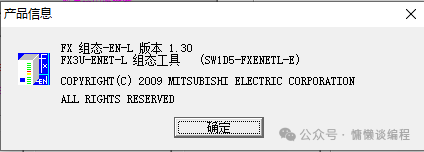 Open the Ethernet module configuration (I am continuing from the previous article where data was sent to the Java application) and click to open the settings.
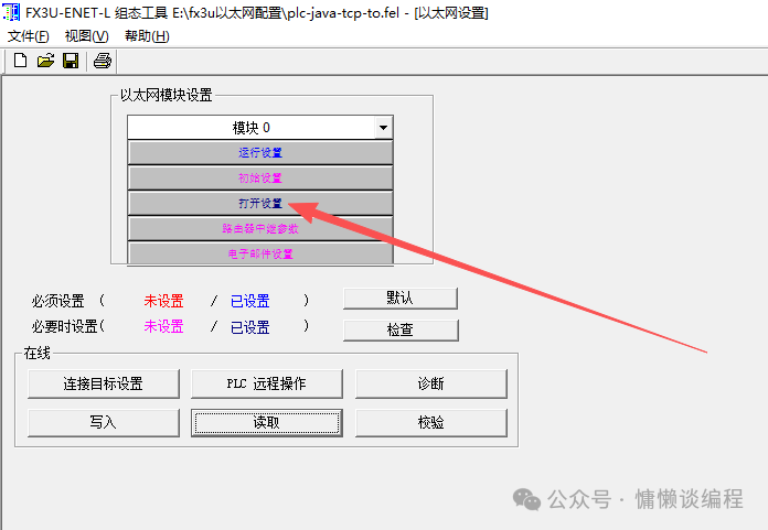 Configure the second buffer to receive data sent from the server.
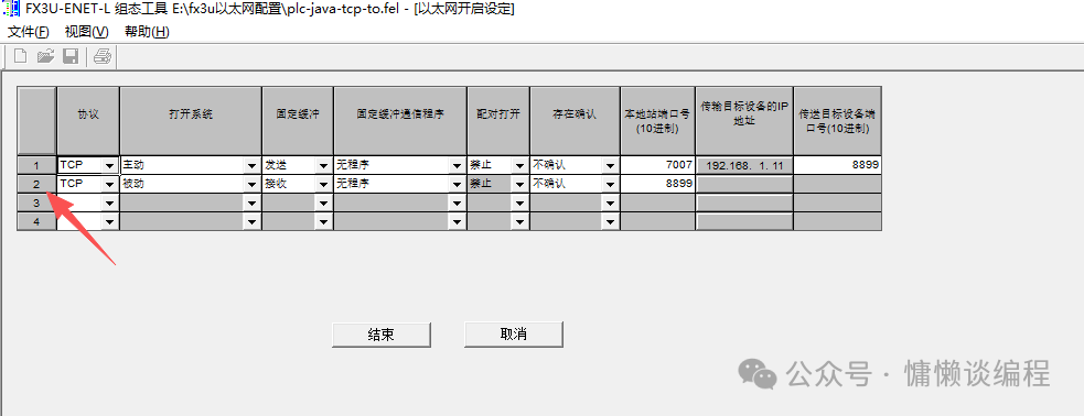 After selecting the second fixed buffer, start the configuration.
Choose TCP or UDP protocol based on specific business needs. This article discusses the TCP method, so we will configure it as TCP.
Open mode: Select passive.
Fixed buffer: Select receive.
Fixed buffer communication program: Select unordered (must select unordered unless you are very familiar with the MC protocol message).
Pair open: Prohibit.
Existence confirmation: No confirmation.
Local port number: Set the port number for the PLC to receive data.
Transmission target device IP address: No need to fill in.
Transmission target device port number: No need to fill in.
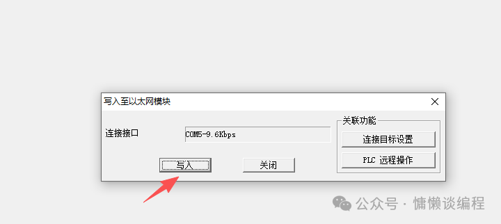
After completing the configuration, save and write to the PLC.
 Write the PLC program to receive byte data.Program Segment 1
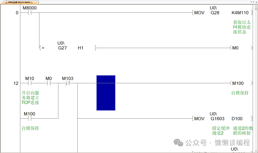 Program Segment 2
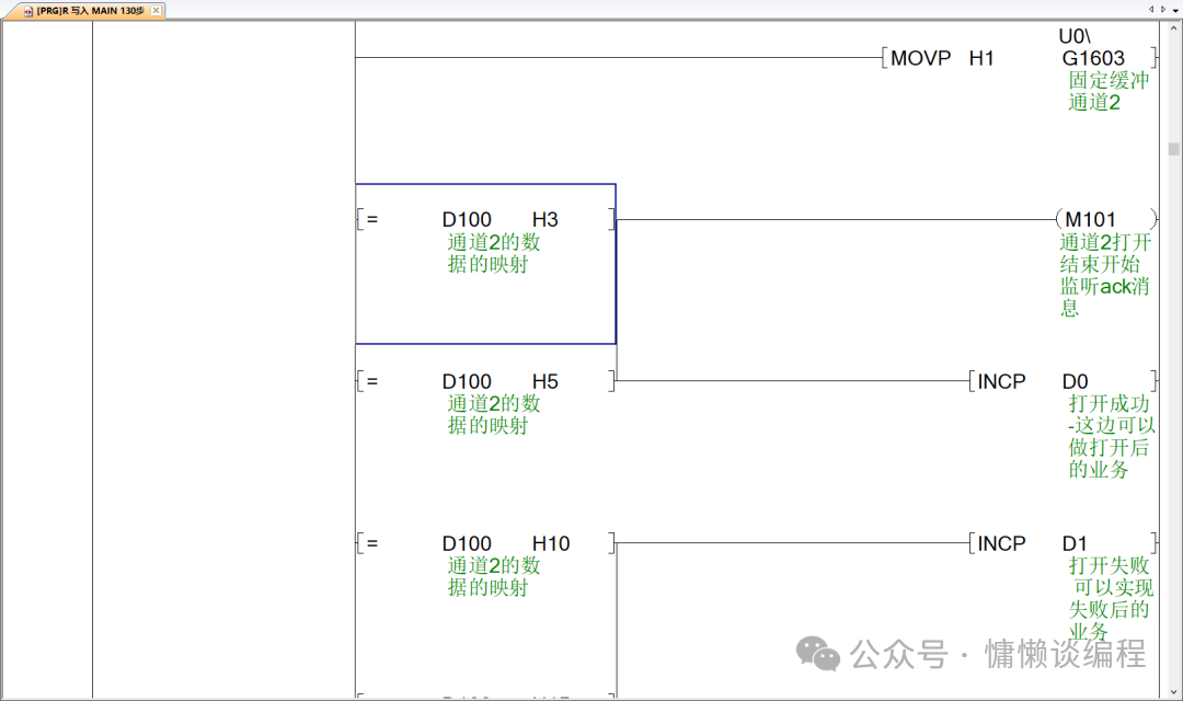 Program Segment 3
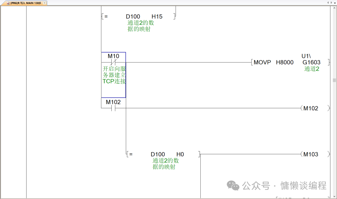 Program Segment 4
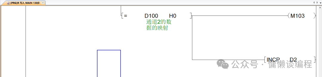 Program Segment 5
 Program Segment 6
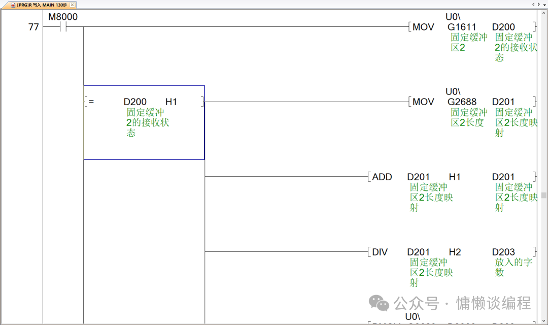
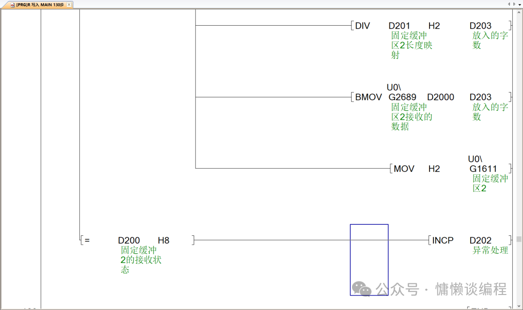 Let’s understand the ladder diagram of the PLC above.The ladder diagrams of Program Segments 1 to 4 serve to open Fixed Buffer 2, acting as a server to listen for messages from the Java client, triggered by the soft element M10.Program Segments 5 to 6 are used to receive the byte array sent by the Java client. First, it checks whether the fixed buffer is in a state to receive data. If it can receive data, it retrieves the byte count from the fixed buffer, converts the byte length into words (2 bytes = 1 word), and then places the data from the fixed buffer into D2000~ based on the calculated word length. For example, if it calculates that there are 16 words, then D2000~2015 will contain the received data.Java Program
public static void main(String[] args) {        String hostname = "192.168.1.254";  // Server address        int port = 8899;                // Same port number as the server
        try (Socket socket = new Socket(hostname, port)) {            // Get output stream to send data to the server            OutputStream output = socket.getOutputStream();
            // Directly send 1 byte of data 11            byte value = 13;            output.write(value);            output.flush();
            System.out.println("Data sent to server: " + value);
            // Get input stream to receive data from the server            InputStream input = socket.getInputStream();            BufferedReader reader = new BufferedReader(new InputStreamReader(input));
            String response = reader.readLine();            System.out.println("Received response from server: " + response);
        } catch (IOException ex) {            System.err.println("Client error: " + ex.getMessage());            ex.printStackTrace();        }    }
Next, we will demonstrate how they communicate according to the above configuration.PLC Side – As ServerUse Mitsubishi PLC programming software to enable listening mode on the PLC.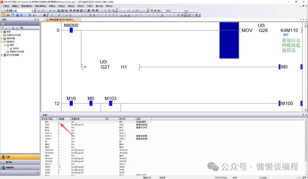 Before sending data with the Java application, we first open the packet capture tool, and for demonstration, we opened two instances.We input the filtering commands:
ip.dst==192.168.1.254 to filter the receiver
ip.src==192.168.1.254 to filter the sender
Java Side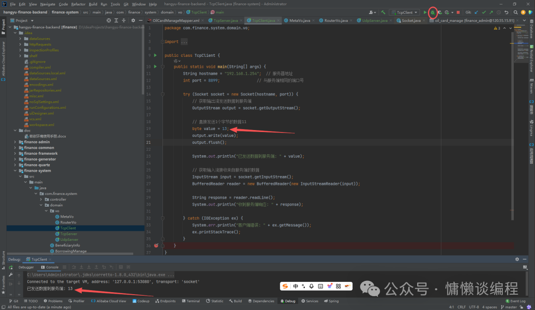 Click debugSend the number 13 and set it to 1 byte.Use the packet capture tool to capture the TCP protocol.
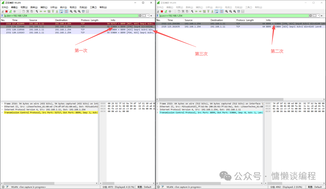 First, perform a three-way handshake. After success, data can be sent.The Java application sends data 13 = 0d.
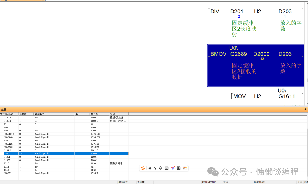 The Mitsubishi PLC programming software shows that the D2000 monitored by the PLC matches the number sent by the Java application, which is also 13.Thus, the operation of writing data into the PLC via the TCP protocol from the Java application is complete. Subsequent operations can be performed on the equipment based on the on-site process.The PLC source code can be found at this link:
https://pan.baidu.com/s/13DhxfmzY62igMX6lEvz26Q?pwd=c4haI hope my article is helpful to you.In the next article, I will explain how to write data into the PLC using the UDP protocol from a Java application.