Basic Controls on the Front Panel
Typically, oscilloscopes are operated using the knobs and buttons on the front panel. In addition to the controls on the front panel, many high-end oscilloscopes are now equipped with an operating system, allowing them to be operated like a computer. You can connect a mouse and keyboard to the oscilloscope and use the mouse to control the drop-down menus and buttons on the display to adjust the controls. Additionally, some oscilloscopes come with touch screens, allowing you to access menus using a stylus or your fingertips.
Before Getting Started……
When you first sit down next to the oscilloscope, check whether the input channel you are using is turned on. Press the [Default Settings] button (if available). This will return the oscilloscope to its original default state. Then press the [Autoscale] button (if available). This function will automatically set the vertical and horizontal scales if your waveform is not displayed well on the screen. From this starting point, make any necessary adjustments. If you lose track of the waveform or find it difficult to display, repeat these steps. Most oscilloscopes have at least four main areas on the front panel: vertical controls, horizontal controls, trigger controls, and input controls.
Vertical Controls
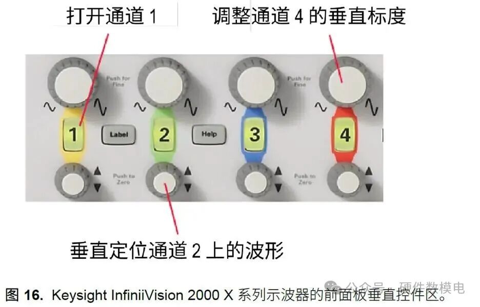
Vertical controls on the oscilloscope are usually located in the area marked with the word “Vertical”. These controls allow you to adjust the display in the vertical direction. For example, there is a control to specify the voltage per division on the y axis of the display grid. You can magnify the waveform by decreasing the voltage per division or shrink the waveform by increasing this number. There is also a control for vertical offset of the waveform. This control can shift the entire waveform up or down on the display. You can see the vertical control area of the Keysight InfiniiVision 2000 X series oscilloscope in Figure 16.
Horizontal Controls
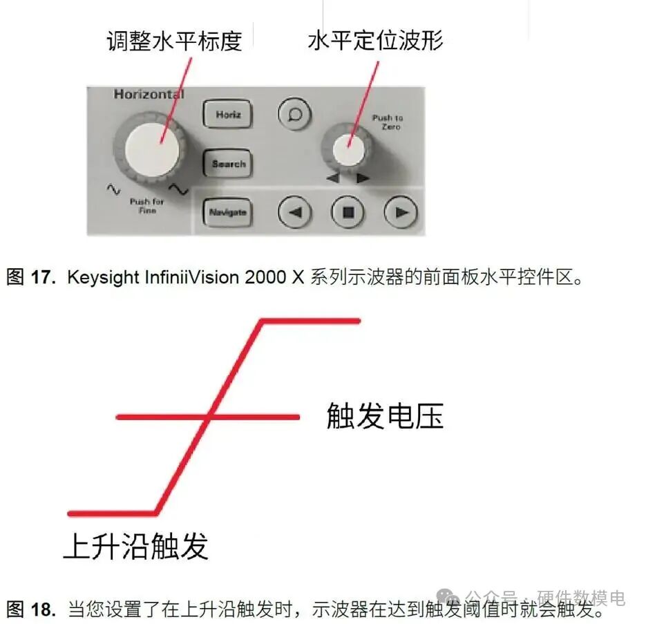
Horizontal controls on the oscilloscope are usually located in the area marked with the word “Horizontal”. These controls allow you to adjust the horizontal scale of the display. There is a control to specify the time per division on the x axis. Similarly, decreasing the time per division allows you to zoom in on a narrower time range. This area also has a control for horizontal delay (offset). This control allows you to scan a time period. You can see the horizontal control area of the Keysight InfiniiVision 2000 X series oscilloscope in Figure 17.
Pulse Width Triggering
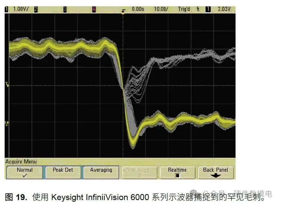
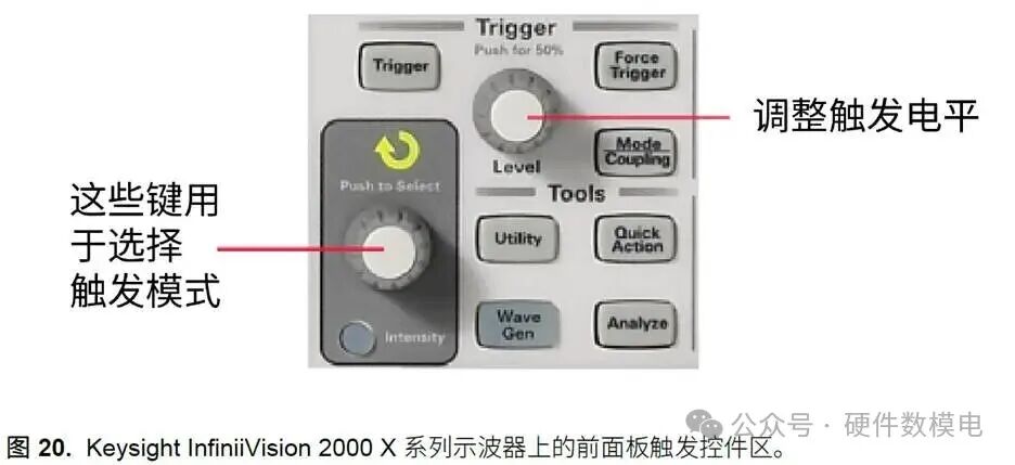
When you need to find a specific pulse width, pulse width triggering is similar to glitch triggering. However, you can typically trigger on any specified width pulse and choose the polarity (negative or positive) of the pulse to trigger on. You can also set the trigger level. This way, you can see what happens before and after the trigger. For example, you can perform glitch triggering to find the error and then look at the signal before the trigger to determine the cause of the glitch. If you set the horizontal delay to zero, the trigger event will be placed in the middle of the screen horizontally. Events that occurred before the trigger will be on the left side of the screen, while events that occurred after the trigger will be on the right side. You can also set the trigger coupling and specify the input source you want to trigger on. You do not have to trigger on your own signal; you can also trigger on related signals. Figure 20 shows the trigger control area on the front panel of the oscilloscope.
Input Controls
Oscilloscopes typically have two or four analog channels. These channels are numbered, and each specific channel usually has a corresponding button to turn that channel on or off. Additionally, there may be an option to specify AC or DC coupling. If you choose DC coupling, the entire signal will be input. Conversely, AC coupling will block the DC component, centering the waveform around 0 volts (ground). Furthermore, you can specify the probe impedance for each channel using a selection button. The input controls also allow you to select the type of sampling. There are two basic methods of signal sampling:
•Real-time Sampling
Real-time sampling typically collects enough waveform samples to capture a complete image of the waveform with each acquisition. Using real-time sampling, some of today’s higher-performance oscilloscopes can capture bandwidth signals of up to 32GHz in a single acquisition.
•Equivalent Time Sampling
Equivalent time sampling builds the waveform by sampling multiple acquisitions. In the first acquisition, a portion of the signal is sampled, then in the second acquisition, another portion is sampled, and so on. All this information is then combined to reconstruct the waveform. Equivalent time sampling is very useful for high-frequency signals that are too fast to sample in real-time (> 32 GHz).
Soft Keys
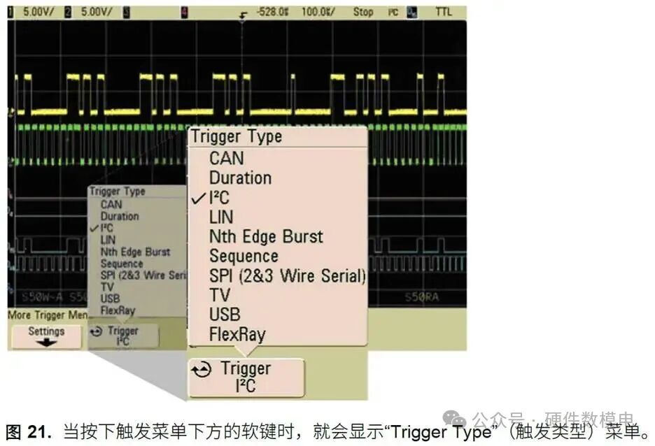
Soft keys often appear on oscilloscopes that do not have the Windows operating system installed (see soft key image in Figure 8). Using these soft keys allows you to navigate the menu system on the oscilloscope display. Figure 21 shows what the drop-down menu looks like when a soft key is pressed. The menu displayed is for selecting the trigger mode. You can scroll through the options by continuously pressing the soft keys, and there is a knob on the front panel that is also used for scrolling through the options.
Important Performance Indicators of Oscilloscopes
Many performance indicators of oscilloscopes significantly affect the performance of the instrument, which in turn affects the ability to accurately test devices. This section will cover the basics of these indicators. This content will also help you become familiar with oscilloscope terminology and make informed decisions when selecting the most suitable oscilloscope.
Bandwidth
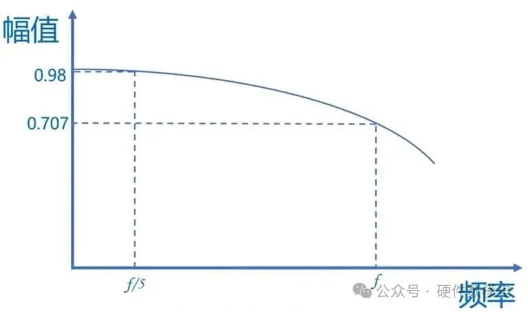
Bandwidth is one of the most important characteristics of an oscilloscope because it indicates the frequency range of the oscilloscope. In other words, it determines the range of signals that can be accurately displayed and tested (in terms of frequency). Bandwidth is measured in Hz. If the bandwidth is insufficient, the oscilloscope will not be able to accurately display the actual signal. For example, the amplitude of the signal may be incorrect, edges may be unclear, and waveform details may be lost. The bandwidth of the oscilloscope is the minimum frequency at which the input signal is attenuated by 3dB. Another way to view bandwidth is: if you input a pure sine wave into the oscilloscope, the bandwidth is the minimum frequency at which the displayed amplitude is 70.7% of the actual signal amplitude. It is recommended that the bandwidth of the oscilloscope should be at least 5 times greater than the signal being measured (Why five times? ① For sine signals, when the bandwidth of the oscilloscope is five times that of the measured signal, the signal amplitude attenuation is only 2%, which is almost negligible; ② For square wave signals, it is generally recommended that the bandwidth of the oscilloscope be ten times that of the measured signal).
Number of Channels
The channels refer to the independent input terminals of the oscilloscope. The number of channels on an oscilloscope typically ranges from 2 to 20 channels. Typically, there are 2 or 4 channels. The types of signals carried by the channels can also vary. Some oscilloscopes only have digital channels (these instruments are called DSO, or digital storage oscilloscopes). Others are called mixed signal oscilloscopes ( MSO), which have both analog and digital channels. For example, the Keysight InfiniiVision series MSO has 20 channels, of which 16 are digital channels and 4 are analog channels.
It is crucial to ensure that there are enough channels for your application. If there are two channels but you need to display four signals simultaneously, there will obviously be a problem.
Sampling Rate
The sampling rate of an oscilloscope is the number of samples it can collect per second. It is recommended that the sampling rate of the oscilloscope should be at least 2.5 times its bandwidth. However, ideally, the sampling rate should reach 3 times or higher than the bandwidth.
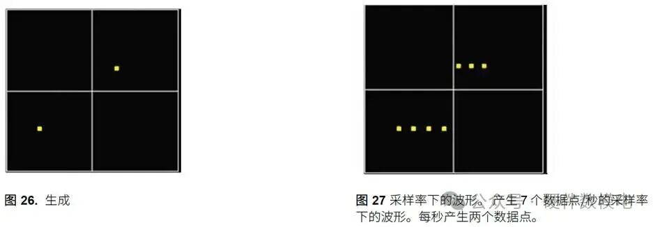
Be cautious when evaluating the sampling rate specifications claimed by the oscilloscope. Manufacturers often refer to the maximum sampling rate that the oscilloscope can achieve, but sometimes this maximum sampling rate is only achievable when using one or two channels. If more channels are used simultaneously, the sampling rate may decrease. Therefore, it is best to confirm how many channels can be used while maintaining the specified maximum sampling rate. If the sampling rate of the oscilloscope is too low, the signal you see on the oscilloscope will be less accurate. For example, if you want to view a waveform but the sampling rate is low, the oscilloscope may only generate two points per cycle (Figure 26).
For the same waveform, increasing the sampling rate allows for seven samples per cycle (Figure 27).
Clearly, the higher the number of samples per second, the clearer and more accurate the waveform display. If we keep increasing the sampling rate in the above example, the sampling points will eventually appear almost continuous. In fact, oscilloscopes typically use sin(x)/x interpolation between sampling points.
Memory Depth
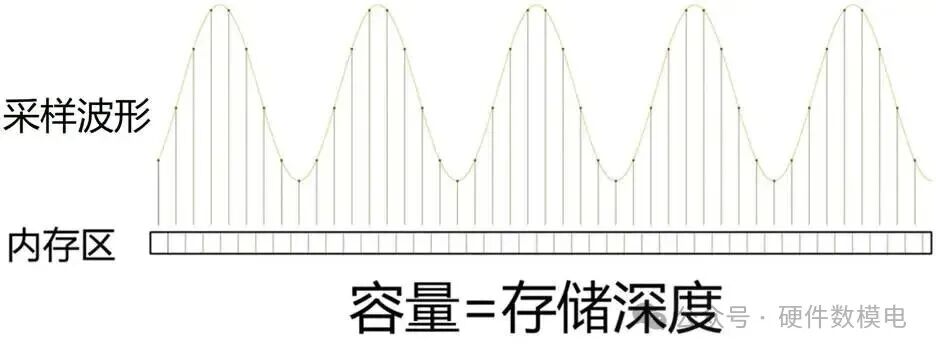
As mentioned earlier, digital oscilloscopes use A/D (analog-to-digital) converters to digitize the input waveform. The digitized data is then stored in the oscilloscope’s high-speed memory. Memory depth refers to how many samples or points can be stored and how long they can be stored.
Memory depth plays an important role in the sampling rate of the oscilloscope. Ideally, the sampling rate should remain constant regardless of the settings of the oscilloscope. However, such oscilloscopes require a large amount of storage space to achieve large time/grid settings, making them expensive and significantly limiting the number of customers who can afford them. Conversely, the sampling rate decreases as the time range increases. Memory depth is important because the greater the memory depth of the oscilloscope, the longer it can capture waveforms at full sampling speed. Mathematically, this can be expressed with the following formula:
Memory Depth = (Sampling Rate)*(Display Time)
For example:
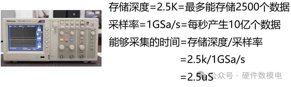
Suppose an oscilloscope has a memory depth of 2.5K, which means it can store a maximum of 2500 data points.
Sampling Rate=1GSa/s= sampling 1 billion data points per second.
The time that can be captured or the display time= Memory Depth / Sampling Rate= 2.5K / 1GSa/s = 2.5us
Thus, we can only sample 2.5us of data length before the storage is full, but in many measurement cases, we need to observe longer data lengths, at which point the oscilloscope will actively reduce its sampling frequency. For example, if we need 1ms waveform, the sampling rate at this time= Memory Depth/ Time=2.5K/ 1ms = 2.5MSa/s, then the sampling rate of the oscilloscope is 2.5MSa/s, which is significantly lower than the oscilloscope’s maximum sampling rate of 1GSa/s. This example shows that the sampling rate indicated on the oscilloscope is only the maximum sampling rate, while the actual sampling rate during testing is a dynamically adjusted value based on the display time.
Therefore, if you want to observe long periods with high resolution between two points, a deep memory is required. Additionally, it is also important to check the oscilloscope’s response performance when using the deepest memory depth settings. In this mode, the waveform capture performance of the oscilloscope typically declines significantly, so many engineers only use deep memory when necessary.
Waveform Capture Rate
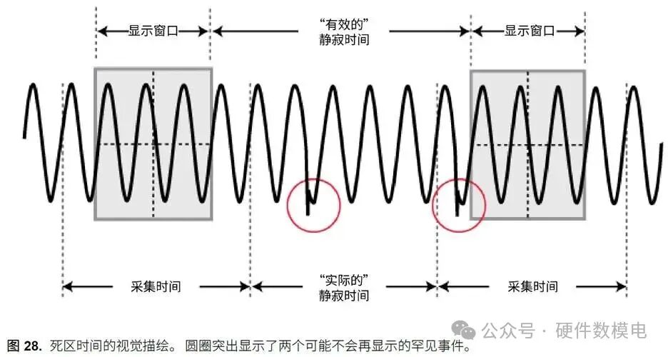
Waveform capture rate refers to the rate at which the oscilloscope can collect and update the waveform display. Although to the human eye, the oscilloscope appears to display “real-time” waveforms, this is because the update rate is so fast that the human eye cannot perceive the changes. In reality, there are some dead times between waveform acquisitions (Figure 28). During this quiet time, part of the waveform is not displayed on the oscilloscope. Therefore, if a rare event or glitch occurs during one of these quiet moments, you will not see it.
This illustrates why a fast waveform capture rate is important. The faster the waveform capture rate, the shorter the dead time, which means a higher probability of capturing rare events or glitches.
For example, suppose you are displaying a signal that has a glitch occurring once every 50000 cycles. If the oscilloscope’s waveform capture rate is 100000 waveforms per second, then on average, you will capture this glitch twice per second. Conversely, if the oscilloscope’s waveform capture rate is 800 waveforms per second, then on average, it will take a minute to capture it once. This observation time is too long.
Oscilloscope Connectivity
Oscilloscopes have a wide range of connectivity features. Some oscilloscopes come equipped with USB ports, DVD-RW drives, external hard drive ports, external monitor ports, etc. All these features make it easier for you to use the oscilloscope and transfer data. Some oscilloscopes are also equipped with an operating system, allowing the oscilloscope to operate like a PC. You can view the oscilloscope’s display and control it using an external monitor, mouse, and keyboard, as if it were embedded in a PC case. In many cases, you can also transfer data from the oscilloscope to a PC via USB or LAN.
Good connectivity can save you a lot of time and make it easier to get your work done. For example, it allows you to quickly and seamlessly transfer data to a laptop or share data with colleagues in different geographical locations. Good connectivity also allows you to remotely control the oscilloscope via a PC. In summary, in a world where efficient data transfer is often required, purchasing an oscilloscope with high-quality connectivity is a very good investment.
Oscilloscope Probes
The oscilloscope is just one part of the testing system, and it determines the accuracy with which you can display and analyze signals. The probes used to connect the oscilloscope to the device under test (DUT) are also crucial for signal integrity. If you have a 1GHz oscilloscope but only a probe that supports 500MHz bandwidth, you will not be able to fully utilize the bandwidth of the oscilloscope. This section will discuss the types of probes and when each type should be used.
No probe can perfectly reproduce your signal because when you connect the probe to the circuit, the probe becomes part of that circuit. Some electrical energy in the circuit will flow through the probe. This phenomenon is called loading effect. There are three types of loading: resistive loading, capacitive loading, and inductive loading.
Resistive Loading
May cause the displayed signal amplitude to be incorrect. When the probe is connected, it may also cause faulty circuits to start working. It is best to ensure that the probe’s resistance is more than ten times the internal resistance of the power supply, so that the amplitude drop rate is less than 10%.
Capacitive Loading
Can cause slower rise times and reduced bandwidth. To reduce capacitive loading, choose a probe with a bandwidth at least five times that of the signal bandwidth.
Inductive Loading
Can cause ringing in the signal. This is caused by the inductive effect of the probe’s ground wire, so use the shortest possible lead.
Probe Classification
Passive Probes
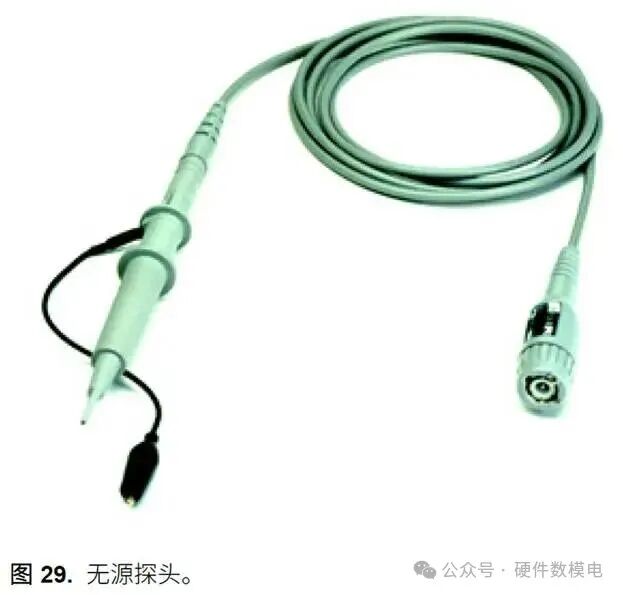
Passive probes only contain passive components and can operate without a power supply. Passive probes are useful for detecting signals with bandwidths less than 600 MHz. Once the frequency exceeds this, a different type of probe (active probe) is required.
Passive probes are usually inexpensive, easy to use, and durable. They are a versatile and accurate type of probe. Passive probes include low-impedance resistive divider probes, compensated probes, high-impedance passive divider probes, and high-voltage probes.
They typically produce relatively high capacitive loading and low resistive loading.
Active Probes
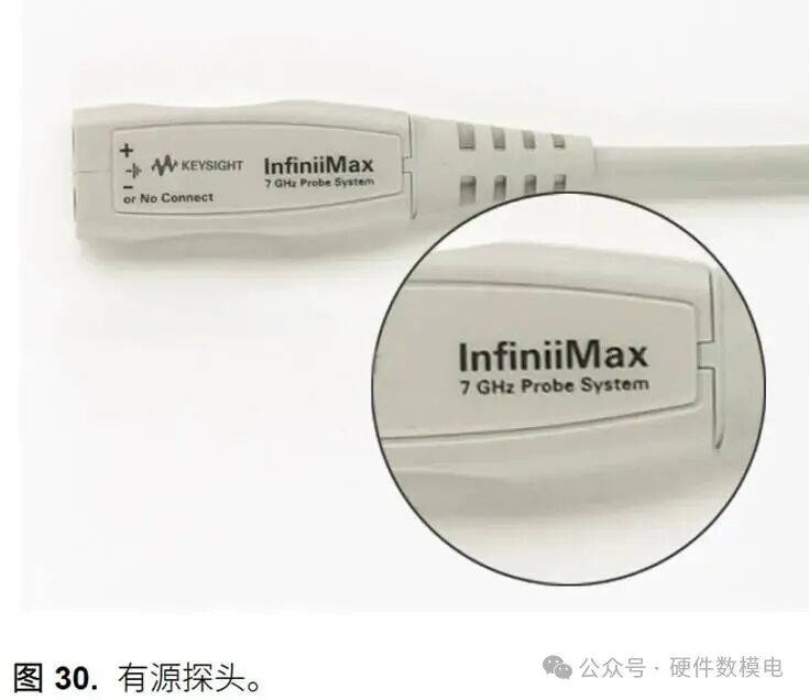
When using active probes, the probe requires a power supply to power its active components. The required power supply is sometimes provided by a USB cable connection (external “box” support) or sometimes provided by the oscilloscope host itself. Active probes use active components to amplify or adjust the signal. They can support much higher signal bandwidths, making them the preferred choice for high-performance applications.
Active probes are significantly more expensive than passive probes, but they are not as durable as passive probes, and the probe tips are often heavier. However, they can provide excellent resistive and capacitive loading performance, allowing you to test signals at much higher frequencies.
Keysight InfiniiMax series probes are considered high-performance probes. They use damping resistors at the probe tip to significantly reduce loading effects. They also have extremely high bandwidth.
Current Probes
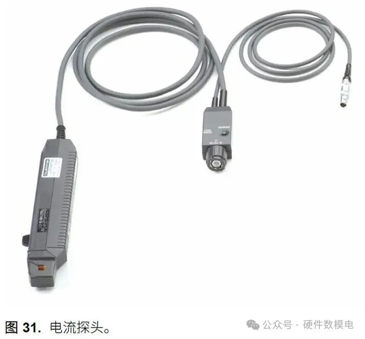
Current probes are used to measure the current flowing through a circuit. They tend to be large and have limited bandwidth ( 100 MHz).
Probe Accessories
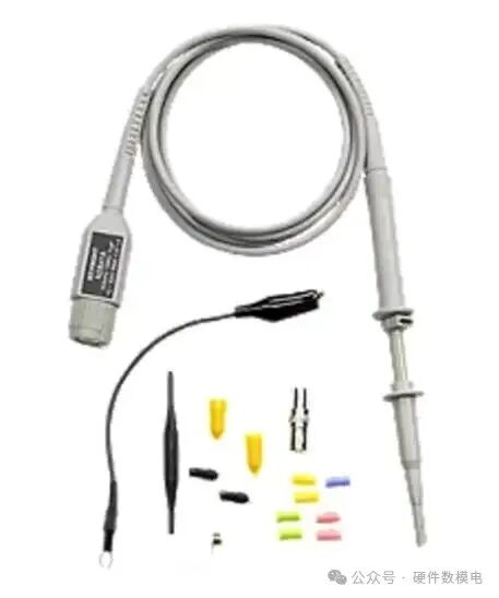
Probes also come with various probe tips. Probe tips come in many different types, from bulky tips that can wrap around cables to tips that are only as thick as a few strands of hair. These probe tips can make it easier to access different parts of the circuit or device under test, and can be used to test power supply ripple, etc. They are easy to lose, so be sure to keep them safe.
Wherever you are, learning is your greatest asset. Thank you for reading, and feel free to follow us.