
Accurate measurement begins at the probe and probe end. Probes that match the oscilloscope and the device under test (DUT) can capture complete signals into the oscilloscope for maximum signal fidelity and measurement accuracy. To measure typical signals and voltage levels, passive probes can provide easy-to-use and various measurement capabilities at a reasonable price. However, ordinary passive probes cannot accurately measure the highest-speed rising signals, which can lead to overload in high-speed circuits being tested. To measure signals with high rise times, high-speed active or differential probes can provide more precise test results.
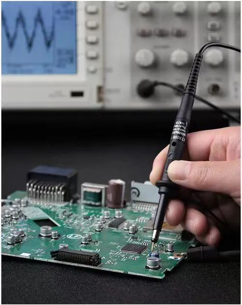
Passive Probes
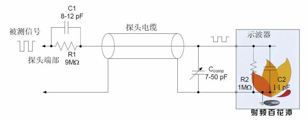
Passive probes are the most common type of probe, typically included with the purchase of an oscilloscope. Common passive probes consist of a probe head, probe cable, compensation equipment or other signal conditioning networks, and a probe connector. These types of probes do not use active components such as transistors or amplifiers, so they do not require power supply. Overall, passive probes are more common, easier to use, and cheaper. Common passive probes can have adjustable attenuation ratios of: 1X, 10X, 100X, and 1000X.Passive voltage probes provide various attenuation factors for different voltage ranges. Among these passive probes, the 10× passive voltage probe is the most commonly used. For applications where the signal amplitude is 1V peak-to-peak or lower, a 1× probe may be more suitable, or even essential. In applications where low and medium amplitude signals mix (from tens of millivolts to tens of volts), a switchable 1×/10× probe is much more convenient. However, a switchable 1×/10× probe is essentially two different probes in one, not only differing in attenuation ratio but also in bandwidth, rise time, and impedance (R and C) characteristics. Therefore, these probes cannot perfectly match the input of the oscilloscope and cannot provide the optimal performance achieved by a standard 10× probe.The probe attenuation is expanded by internal resistors to increase the voltage measurement range of the oscilloscope. This internal resistor, when used with the oscilloscope’s input resistance, creates a voltage divider. For example, a typical 10x probe is equipped with an internal 9MΩ resistor, which, when connected to a 1MΩ input impedance oscilloscope, creates a 10:1 attenuation ratio at the input channel of the oscilloscope. This means that the signal displayed on the oscilloscope will be 1/10th of the actual measured signal amplitude, so we often need to set the attenuation ratio in the oscilloscope’s channel settings to 10X as well.
Active Probes
Active probes contain active components like transistors and amplifiers, requiring power support, hence the name active probes.In most cases, the active device is a Field Effect Transistor (FET), which provides very low input capacitance, allowing for high input impedance over a wider frequency range.The specified bandwidth for active FET probes generally ranges from 500MHz to 4GHz.In addition to having a higher bandwidth, the high input impedance of active FET probes allows measurements at unknown impedance test points with a much lower risk of loading effects.Moreover, due to the low capacitance reducing ground effects, longer ground leads can be used.Active probes do not have the voltage range limitations of passive probes.The linear dynamic range of active probes generally lies between ±0.6V to ±10V.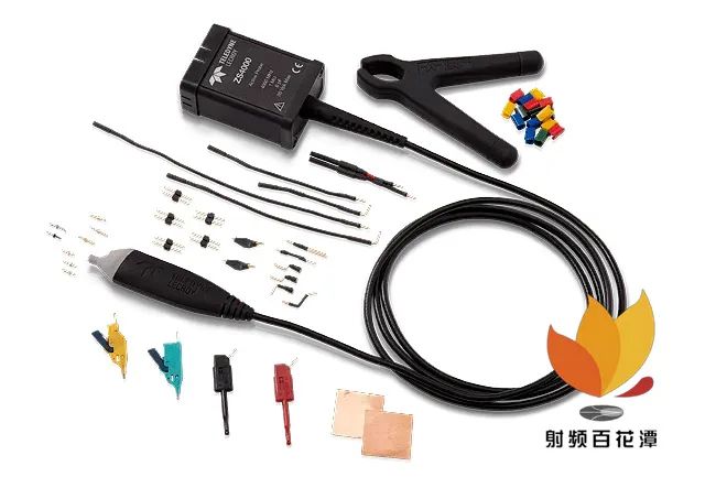
Differential Probes
Active differential probes help you observe differential signals.Differential signals reference each other rather than referencing ground.When using matched single-ended probe pairs, differential probes have better performance, providing high CMRR, wide bandwidth, and minimal time differences between input signals.
High-bandwidth differential probes provide excellent signal fidelity, meeting the needs of engineers in designing and debugging at fast clock rates and clock edge rates.
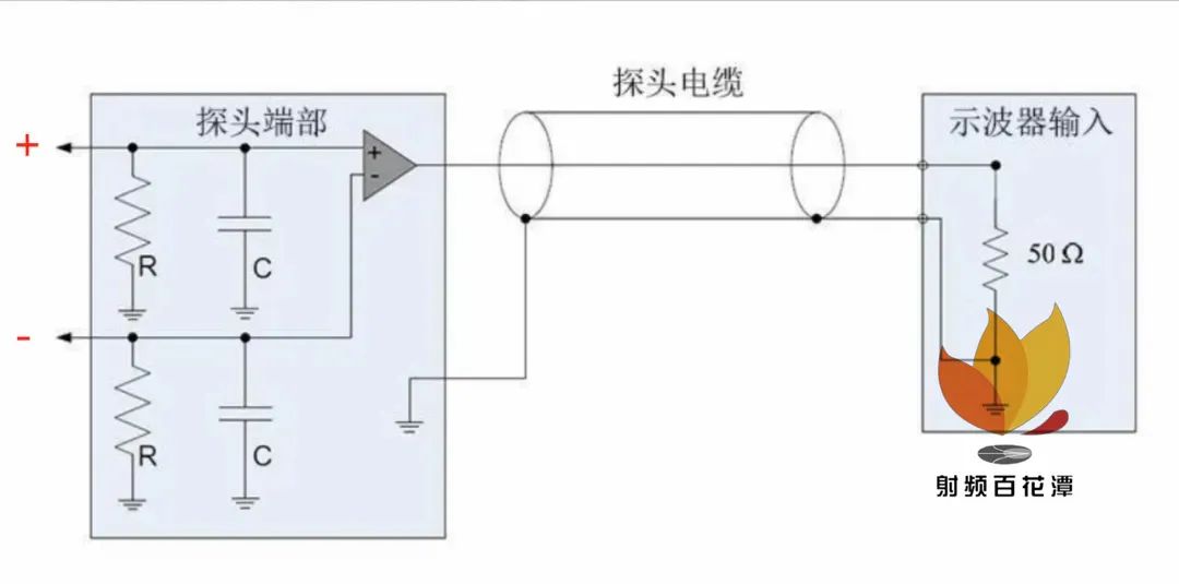
The most apparent advantages of differential signals compared to ordinary single-ended signals are reflected in the following three aspects:
(1) Strong anti-interference capability, as the coupling between the two differential lines is good. When external noise interference exists, it is almost simultaneously coupled to both lines, and the receiving end only cares about the difference between the two signals, thus maximizing the cancellation of external common-mode noise.
(2) Effective suppression of EMI, for the same reason, since the polarities of the two signals are opposite, the electromagnetic fields they radiate can cancel each other out, and the tighter the coupling, the less electromagnetic energy is released to the outside.
(3) Accurate timing positioning, as the switching changes of differential signals occur at the intersection of the two signals, unlike ordinary single-ended signals that rely on high and low threshold voltages for judgment, thus being less affected by processes and temperature, reducing timing errors, and making them more suitable for low-amplitude signal circuits. The currently popular LVDS refers to this type of small amplitude differential signal technology.
The principle of differential amplification refers to a pair of signals input into an amplification circuit simultaneously and then subtracted to obtain the original signal. A differential amplifier is constructed from two transistors with identical parameter characteristics using direct coupling. If equal and in-phase signals are input at both terminals, the output will be zero, thus overcoming zero drift.
Having understood the probes and basic knowledge, we will now showcase the front end of a certain manufacturer’s 20G differential probe in ‘High-End Disassembly’, with excellent design and workmanship, highly commendable:
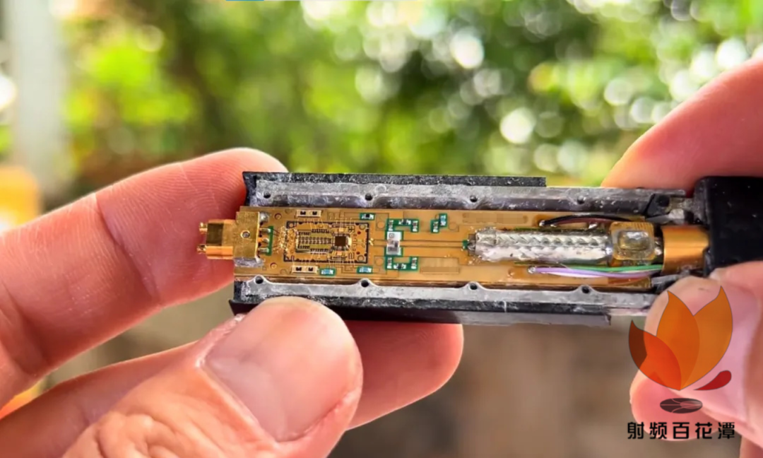
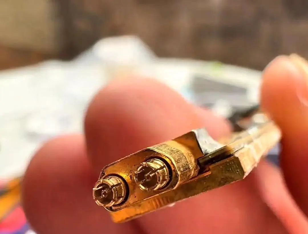
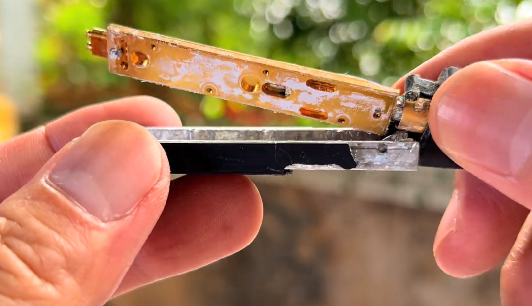
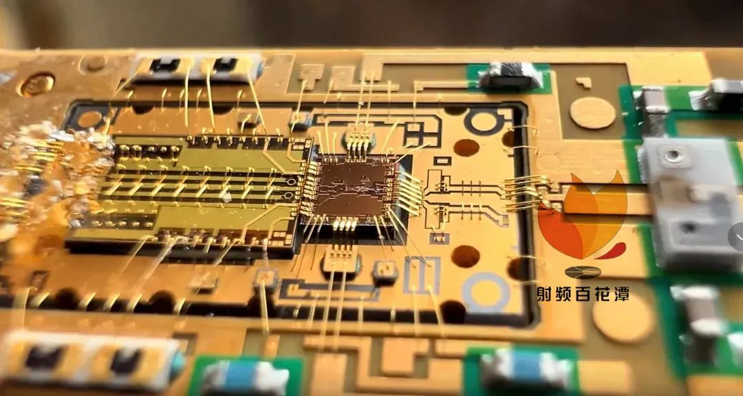
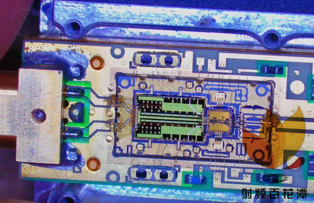
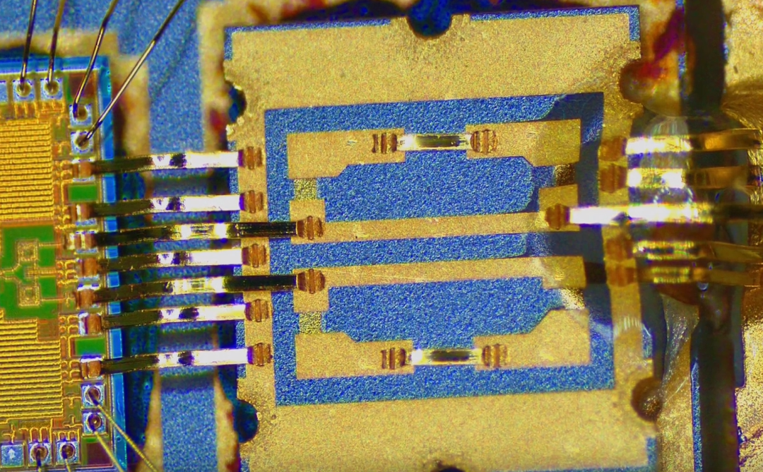
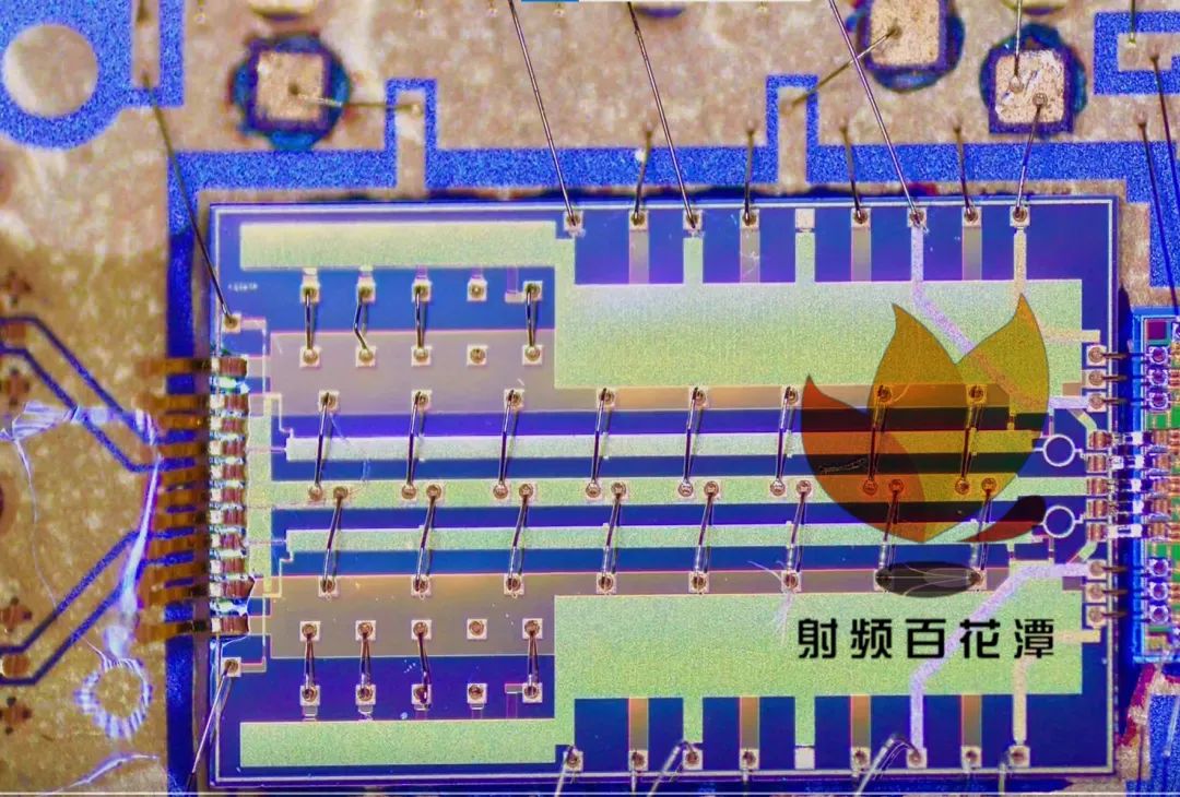
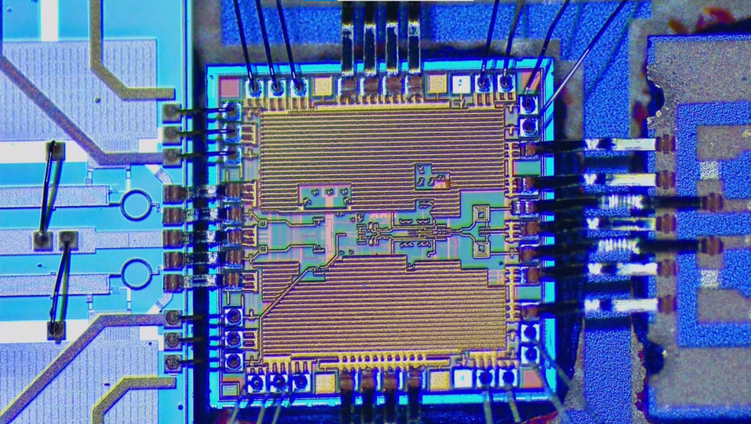
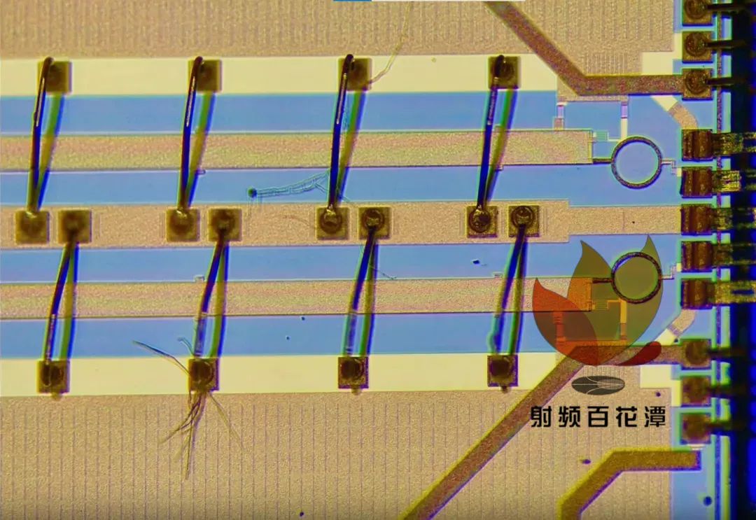
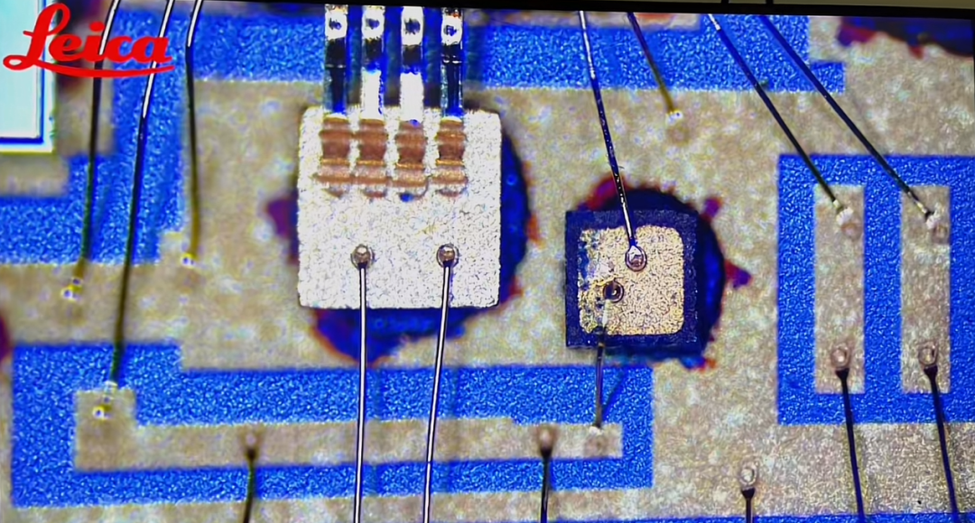
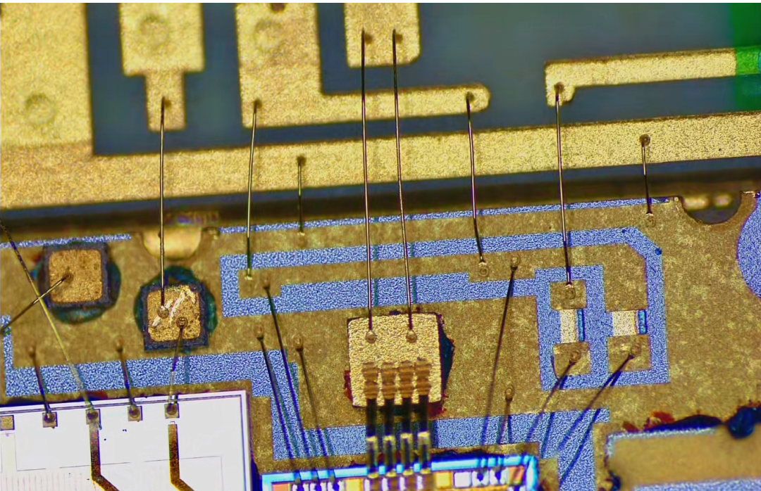
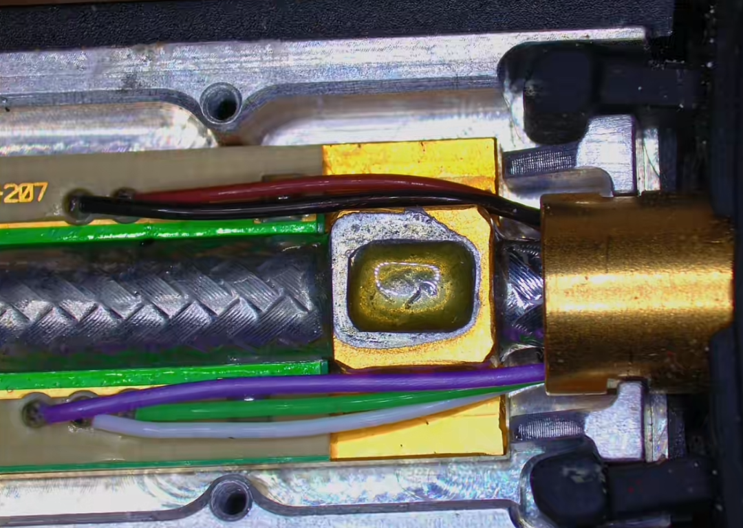
Regarding the above circuits and processes, feel free to leave comments for discussion!

Disclaimer:
This account maintains neutrality regarding all statements and viewpoints in original and reprinted articles. The articles are provided solely for readers’ learning and communication. The copyrights of articles, images, etc., belong to the original authors, and if there is any infringement, please contact for removal.
For submissions/recruitment/promotion/advertising, please add WeChat: 15989459034