“ Infrared remote control technology enables short-range wireless control using infrared light, with the transmitter encoding and sending signals, and the receiver demodulating and decoding them. The NEC protocol is a commonly used standard, which includes frame structures such as lead code, address code, command code, etc., and extended protocols can add data bits. It is cost-effective, technically mature, and widely used in home appliances, smart homes, toys, and other scenarios.”
01
—
Infrared Remote Control Technology
Infrared remote control technology is a wireless control technology that uses infrared light for non-contact signal transmission. It sends encoded infrared signals through an infrared transmitter, which are received and decoded by a receiver to control devices. An infrared remote control system typically consists of a transmitter (including an encoding chip and an LED transmitter) and a receiver (including a photoelectric converter and demodulation circuit).
Infrared remote control is a short-range wireless control technology based on infrared signal transmission, with a wavelength range of 700 nanometers to 1 millimeter, which falls under invisible light. It has strong penetration and anti-interference capabilities, commonly used for short-range communication, such as remote controls and infrared sensors. Its transmission rate is relatively low, but it is inexpensive and technically mature. In contrast, visible light has a wavelength range of 380 nanometers to 750 nanometers, which is visible to the human eye, offering higher transmission rates and broader spectral resources, suitable for high-speed data transmission and indoor positioning applications.
1. Infrared Remote Control Transmitter:
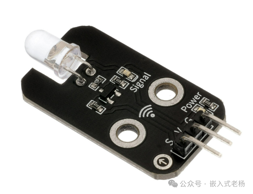
It mainly consists of an encoding chip, power supply, and infrared transmission circuit. It is responsible for converting user commands into specific infrared signals, which are emitted through an infrared LED. Common encoding methods include the NEC protocol.
Application scenarios for the transmitter:
-
Home appliance control: Such as remote controls for TVs, air conditioners, etc., which use specific infrared signals to turn devices on/off and adjust settings.
-
Smart home control: Used to control smart lighting, curtains, and other devices.
-
Toy remote control: Some toy cars, planes, etc., are controlled via infrared remote transmitters.
2. Infrared Remote Control Receiver:
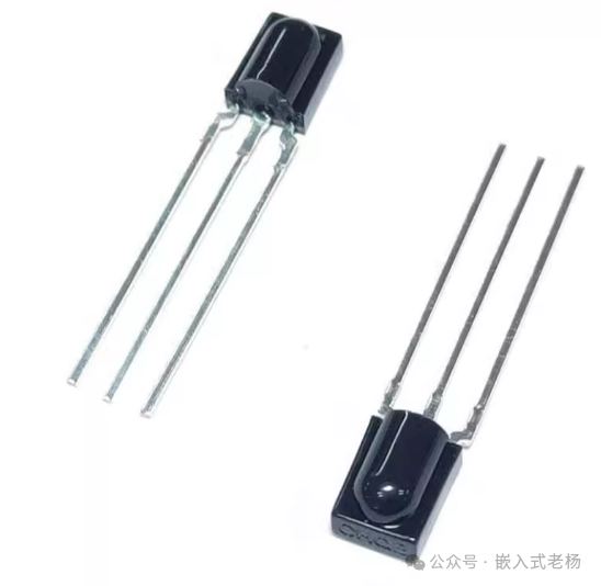
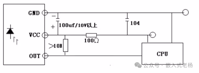
It consists of an infrared receiving circuit, infrared decoding chip (microcontroller), power supply, and application circuit. The receiver converts the received infrared light signals into electrical signals, which are then processed through amplification, limiting, detection, shaping, etc., to form remote control command pulses, output to the microcontroller for decoding.
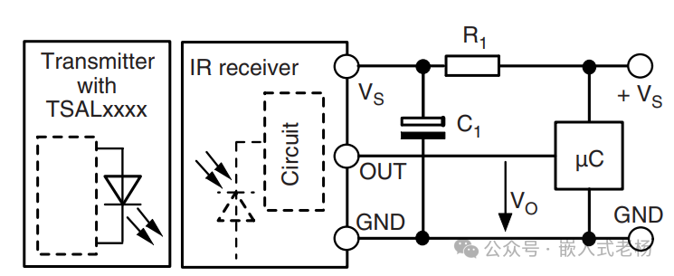
Application scenarios for the receiver:
-
Home appliances: Such as TVs, air conditioners, etc., which have built-in infrared receivers to receive signals from remote controls and perform corresponding actions.
-
Smart home systems: Receives signals from remote controls or other infrared emitting devices to control smart home devices.
-
Industrial control: Used in some industrial equipment to receive control commands for remote operation.
02
—
NEC Protocol Frame
1. Standard NEC 32-bit Frame
The standard NEC protocol is a widely used standard in infrared remote control communication, defining the structure and modulation of data frames. Its data frame includes the following parts:
-
Lead code: 9ms carrier signal + 4.5ms no carrier signal.
-
Address code: 8-bit address code.
-
Address inverse code: Inverse of the 8-bit address code.
-
Command code: 8-bit command code.
-
Command inverse code: Inverse of the 8-bit command code.
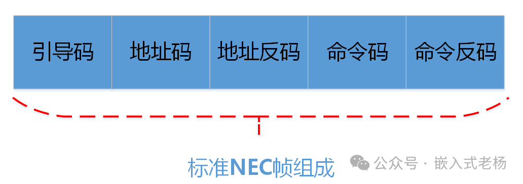
2. NEC Extended Protocol
The NEC extended protocol expands upon the standard NEC protocol, mainly differing in the increase of data bits and the redefinition of some fields.
Frame length:
The extended protocol may increase the number of data bits, for example, expanding from 32 bits to 40 bits or more to support more device addresses and commands.
Data structure:
In addition to the standard address code, address inverse code, command code, and command inverse code, the extended protocol may introduce additional data fields for more complex function control or device identification.
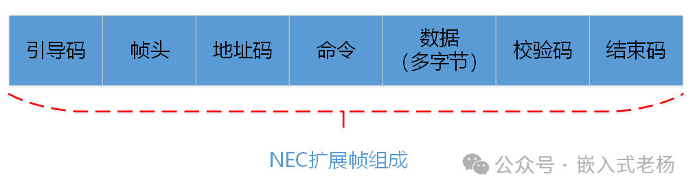
3. Differences between Standard Frame and Extended Frame
Standard NEC 32-bit Frame:
Fixed at 32 bits, including 8-bit address code, 8-bit address inverse code, 8-bit command code, and 8-bit command inverse code.
NEC Extended Protocol:
Frame length may increase, data structure becomes more complex, and may include additional data fields.
4. Sending Frame and Receiving Frame
Sending Frame:
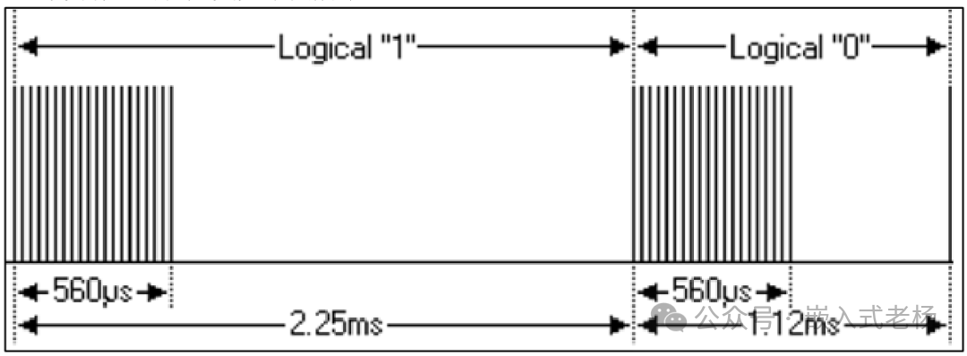
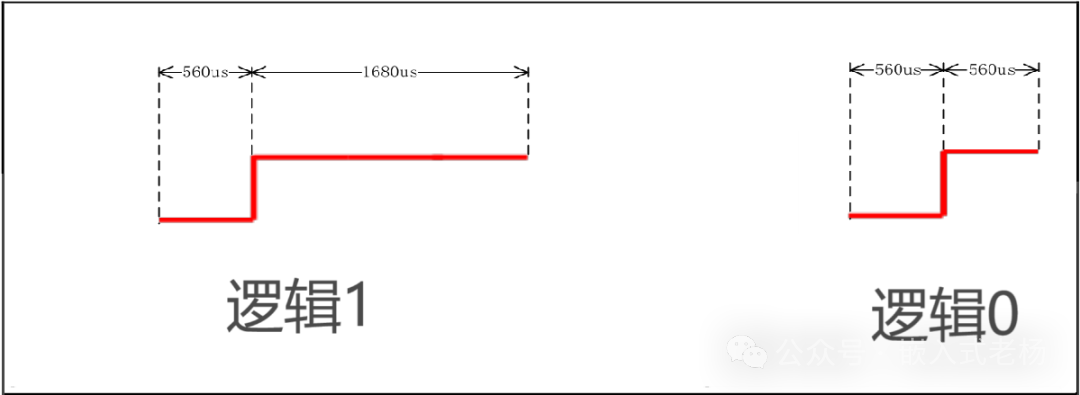
The sending frame consists of lead code, address code, address inverse code, command code, and command inverse code. Logic “0” is represented as a 560us carrier + 560us low level, totaling 1.12ms; logic “1” is represented as a 560us carrier + 1690us low level, totaling 2.25ms.
The lead code of the sending frame typically consists of a 9ms high level (carrier signal) and a 4.5ms low level. The other parts of the sending frame logic levels are shown in the following diagram:
Receiving Frame:
The structure of the receiving frame is the same as that of the sending frame, but due to the characteristics of the receiver, the received signals will differ. For example, the received logic “0” is a 560us low level + 560us high level, and logic “1” is a 560us low level + 1690us high level.
The lead code of the receiving frame typically consists of a pulse sequence of 9ms low level and 4.5ms high level. The other parts of the receiving frame logic levels are shown in the following diagram:
03
—
Application Example
The NEC extended frame for the power-on command of a specific model of air conditioner is as follows:
|
Byte Index |
Meaning |
|
Lead Code |
9ms carrier signal + 4.5ms no carrier signal |
|
0 |
Start Code/Frame Header |
|
1 |
Address (fixed 0x10) |
|
2 |
Command (on/off, mode…) |
|
3 |
Data (temperature, wind speed, sweep, timer, etc.) |
|
11 |
Checksum (verification of bytes 1-10) |
|
12 |
End Code |
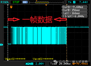
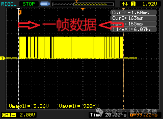
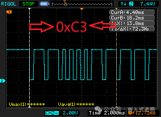
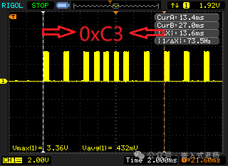
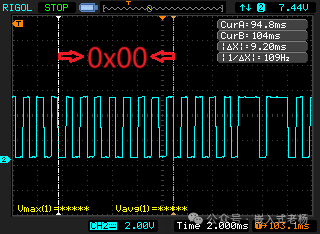
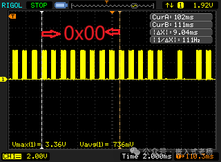
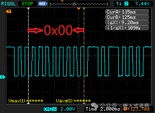
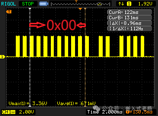
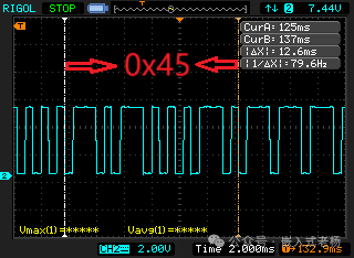
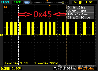
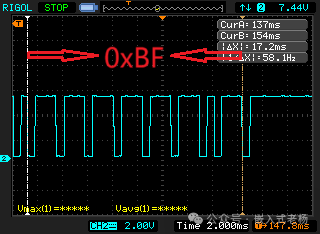
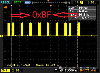
Using an oscilloscope to capture the power-on command, the transmitted frame data of 13 bytes is obtained: 0xC3, 0xC7, 0xE0, 0x00, 0x20, 0x40, 0x80, 0x00, 0x00, 0x30, 0x00, 0x45, 0xBF. The waveform captured by the oscilloscope is shown in the following diagram (LSB-First):
|
Receiving Frame Waveform |
Sending Frame Waveform |
|
|
|
|
|
|
|
|
|
|
|
|
|
|
|
|
|
|
04
—
Program Design
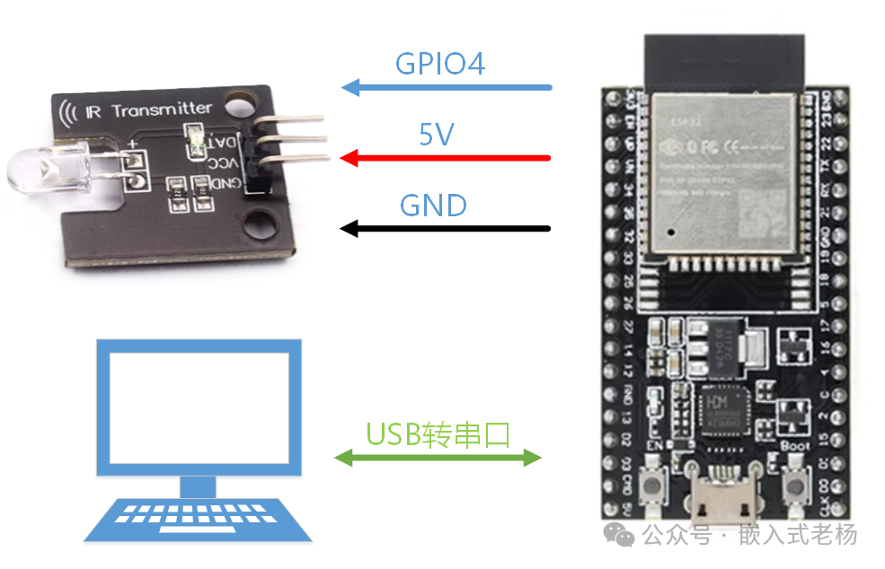
Taking the transmitter as an example, ESP32-S3 GPIO4 is used as the infrared LED data port, sending the air conditioner 104-bit extended protocol frame data: 0xC3, 0xC7, 0xE0, 0x00, 0x20, 0x40, 0x80, 0x00, 0x00, 0x30, 0x00, 0x45, 0xBF every 5 seconds. Each time a frame of data is sent, “frame sent done!” is printed on Serial 0. The sending frame waveform is shown in section 3.
Main function:
void app_main(void){ /* NVS initialization */ esp_err_t ret = nvs_flash_init(); if (ret == ESP_ERR_NVS_NO_FREE_PAGES || ret == ESP_ERR_NVS_NEW_VERSION_FOUND) { ESP_ERROR_CHECK(nvs_flash_erase()); ESP_ERROR_CHECK(nvs_flash_init()); } /* Serial initialization (for debugging) */ usart_init(115200); /* ------------ Configure RMT TX channel ------------ */ rmt_channel_handle_t tx = NULL; rmt_tx_channel_config_t tx_cfg = { .gpio_num = IR_TX_GPIO, .clk_src = RMT_CLK_SRC_DEFAULT, .resolution_hz = 1 * 1000 * 1000, // 1 MHz resolution .mem_block_symbols = 128, .trans_queue_depth = 2, }; ESP_ERROR_CHECK(rmt_new_tx_channel(&tx_cfg, &tx)); /* 38 kHz carrier, 33 % duty cycle */ rmt_carrier_config_t car = { .frequency_hz = CARRIER_HZ, .duty_cycle = 0.33f, }; ESP_ERROR_CHECK(rmt_apply_carrier(tx, &car)); /* Create copy_encoder (send fixed symbol table) */ rmt_encoder_handle_t copy_enc = NULL; rmt_copy_encoder_config_t copy_cfg = {0}; ESP_ERROR_CHECK(rmt_new_copy_encoder(©_cfg, ©_enc)); /* Enable channel */ ESP_ERROR_CHECK(rmt_enable(tx)); /* Pre-generate 106 symbols */ rmt_symbol_word_t symbols[TOTAL_SYMBOLS]; build_aux_symbols(aux_frame, symbols); /* Send every 5 seconds */ while (true) { ESP_LOGI(TAG, "Sending 104-bit frame..."); ESP_ERROR_CHECK(rmt_transmit(tx, copy_enc, symbols, sizeof(symbols), &(rmt_transmit_config_t){0})); ESP_ERROR_CHECK(rmt_tx_wait_all_done(tx, pdMS_TO_TICKS(300))); ESP_LOGI(TAG, "frame sent done!"); vTaskDelay(pdMS_TO_TICKS(5000)); }}Constructing Data Frame:
static void build_aux_symbols(const uint8_t *src, rmt_symbol_word_t *sym){ int idx = 0; /* Lead code: 9 ms high + 4.5 ms low */ sym[idx++] = (rmt_symbol_word_t){ .level0 = 1, .duration0 = 9000, .level1 = 0, .duration1 = 4500 }; /* Continuous 104 bits, MSb first (aux_frame is already ordered) */ for (int i = 0; i < FRAME_LEN * 8; ++i) { int byte = i / 8; int bit = i % 8; // Directly take bit, as the byte is already MSb→LSb uint32_t val = (src[byte] >> bit) & 0x01; if (val) { /* Logic 1: 560 µs high + 1690 µs low */ sym[idx++] = (rmt_symbol_word_t){ .level0 = 1, .duration0 = 560, .level1 = 0, .duration1 = 1690 }; } else { /* Logic 0: 560 µs high + 560 µs low */ sym[idx++] = (rmt_symbol_word_t){ .level0 = 1, .duration0 = 560, .level1 = 0, .duration1 = 560 }; } } /* End code: 560 µs high */ sym[idx++] = (rmt_symbol_word_t){ .level0 = 1, .duration0 = 560, .level1 = 0, .duration1 = 0 };}This article’s case uses the following hardware and software:
1. SOC Model: ESP32-S3-N16R8;
2. Software Development Environment: ESP-IDF 5.3.1, VSCode IDE (VSCodeUserSetup-x64-1.102.1 version);
3. ESP32 Project Version: IDF version (FreeRTOS);
4. Program Download: Type C USB (USB to Serial) interface;
5. This software and hardware case is for personal learning only and not for commercial use.
References for this article:
“ESP32-S3 Technical Reference Manual Version 1.7”;
“ESP32-S3 Series Chip Technical Specification Version 2.0”.