When observing the waveform on the crystal oscillator pins with an oscilloscope, it often happens that the crystal oscillator waveform is not visible on the screen or the characteristics of the waveform are incorrect. This article explains the correct method for measuring the crystal oscillator waveform with an oscilloscope through practical operations.
Through the previous video, we already know that using the ×10 probe setting can increase the measurement range of the oscilloscope. What other uses does this feature have?
When observing the waveform on the crystal oscillator pins with an oscilloscope, it often happens that the crystal oscillator waveform is not visible on the screen or the characteristics of the waveform are incorrect, which is likely due to not using the ×10 probe setting!
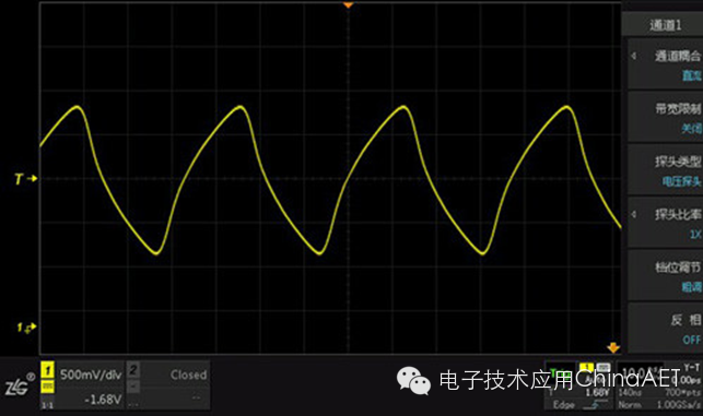
Figure 1: Crystal oscillator waveform observed using the ×1 setting
The crystal oscillator is quite sensitive to capacitive loads. When using the ×1 setting, the probe capacitance is relatively large, which is equivalent to a heavy load being connected in parallel to the crystal oscillator circuit, easily causing the circuit to stop oscillating and resulting in incorrect measurement results.
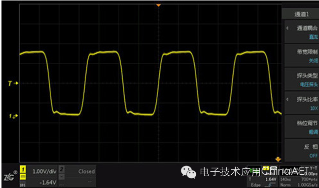 Figure 2: Result of measuring the crystal oscillator waveform using the ×10 setting
The correct approach is to use the ×10 setting for measurement. At this time, the capacitance inside the probe is relatively smaller, which can reduce the load effect introduced by the test. Only then can the measured crystal oscillator waveform be accurate! To improve signal fidelity, the grounding spring supplied with the probe should be used instead of the grounding alligator clip for nearby grounding.
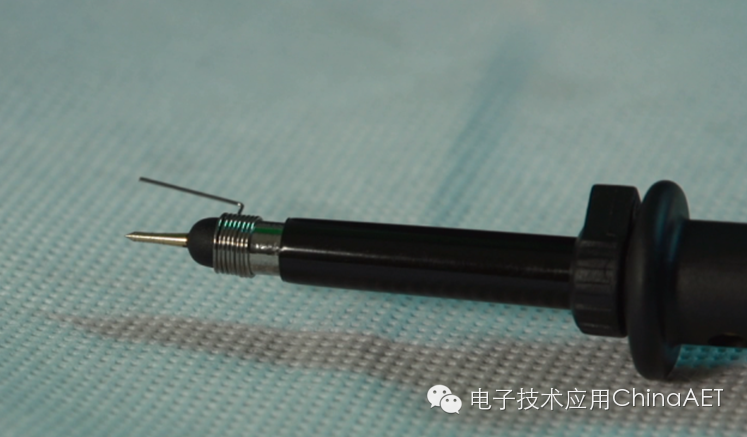 Figure 3: Probe using the supplied grounding spring
On the other hand, the output edge of the crystal oscillator is generally steep, with a short rise time. In essence, the output of the crystal oscillator contains a lot of high-frequency components, so it should be treated as a high-frequency signal and measured with full bandwidth. The bandwidth of the ×1 probe setting is limited, while the ×10 probe setting has full bandwidth enabled, so the ×10 setting must be used for measurement.
To measure signal waveforms accurately, only by using the correct method can the signal be measured accurately, and the conclusions drawn will be meaningful!