Typically, using different types of control valves is one of the interesting parts of a piping network. Therefore, depending on the temperature, pressure, and flow type, the circuit can be automated to control the flow to maintain the desired liquid level or flow rate.
We have used many valves named FV, PV, HV, XV, etc., but we do not know their actual functions and descriptions of the abbreviations. In this article, we will learn about:
- Different control valve abbreviations
- How control valves work
- General design aspects of control valves, etc.
Overall Layout of Control Valves
The installation layout of control valves always includes the following:
- Two isolation valves (usually gate valves) on each side to isolate the flow through the pipeline during any maintenance or repair of the control valve.
- Two drain valves with end caps to drain the fluid in the system before disassembling the control valve.
- One shut-off valve, which acts as a bypass valve when the control valve is inconsistent with the system, and is disassembled during any maintenance or repair work.
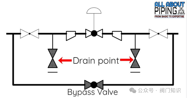
Overall Layout of Control Valves
In many industrial processes that require precise control of fluid flow, control valves are a key component. They regulate the flow of fluids (such as gases, liquids, or slurries) through pipes or channels by adjusting the size of the flow path.
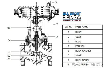
Control valves typically consist of several key components that work together to regulate the fluid’s flow rate, direction, and pressure:
-
Valve Body:
This is the main component of the control valve that provides a passage for fluid flow.
-
Internal Components:
This component interacts with the fluid flow to regulate the flow rate and direction. Internal components include the valve plug, seat, stem, and other internal parts.
-
Actuator:
The actuator generates the force needed to move the stem and control the fluid flow. Actuators can be pneumatic, electric, or hydraulic.
-
Positioner:
This component receives control signals from the controller and adjusts the valve position to maintain the desired flow rate. Positioners can be pneumatic or electronic.
-
Instrumentation:
Instrumentation includes sensors and other devices that measure process parameters such as pressure, temperature, and flow rate. This information is used to provide feedback to the controller and ensure the desired flow rate is maintained.
-
Accessories:
Additional components can be added to the valve, such as manually operated handwheels, limit switches that indicate valve position, or solenoids that control air or electrical signals.
The arrangement of these components may vary depending on the type of control valve and its application. For example, globe valves, ball valves, and gate valves have different arrangements. However, the basic principles remain the same, with the valve body, internal components, actuator, and instruments working together to regulate the fluid flow through the system.
The correct selection and use of control valves are crucial for efficient industrial processes. Control valves help maintain precise and stable flow rates, reduce energy consumption, and optimize process performance.
Overall, control valves are a complex system made up of multiple components working together to regulate fluid flow in industrial processes. It is essential to choose and operate the correct control valve for applications to achieve optimal process performance.
Working Principle of Control Valves
The working principle of control valves is to control the flow of fluids by adjusting the size of the flow path. The valve body provides a path for fluid flow, while the internal components regulate the flow rate and direction. Internal components include things like valve plugs, seats, stems, and other internal parts that interact with fluid flow to regulate flow rates.
The valve actuator generates the force needed to move the stem and control fluid flow. Depending on the application requirements, the actuator can be pneumatic, electric, or hydraulic. When a control signal is received, the actuator moves the stem, changing the position of the internal components and thereby regulating the fluid flow.
The valve positioner receives control signals from the controller to determine the desired flow rate. The positioner then adjusts the valve position to maintain the desired flow rate. Depending on the application requirements, the positioner can be pneumatic or electric.
The instrumentation of control valves includes sensors and other devices that measure process parameters such as pressure, temperature, and flow rate. This information is used to provide feedback to the controller and ensure the desired flow rate is maintained.
Types of Actuators for Control Valves
Control valves use various types of actuators to control fluid flow. These actuators generate the force needed to move the stem and adjust the size of the flow path. The most common types of actuators for control valves are pneumatic, electric, hydraulic, and electromechanical.
-
Pneumatic Actuators:
These use compressed air as a power source to move the stem and regulate fluid flow. They are typically used for medium to small valves, are cost-effective, and easy to implement. On the other hand, electric actuators use electricity to move the stem and control fluid flow. They are more precise than pneumatic actuators and are often used for larger valves that require precise control.
-
Hydraulic Actuators:
These use hydraulic oil as a power source to move the stem and control fluid flow. They are commonly used in high-pressure applications or situations requiring precise control. Electromechanical actuators combine the precision of electric actuators with the power of hydraulic actuators. They use an electric motor to drive a hydraulic pump to power the actuator.
-
Electric Actuators:
These actuators use electricity to move the stem and control fluid flow. Electric actuators are more precise than pneumatic actuators and are typically used for larger valves that require precise control.
-
Electromechanical Actuators:
These actuators combine the precision of electric actuators with the power of hydraulic actuators. They use an electric motor to drive a hydraulic pump to power the actuator.
Choosing the right actuator for a control valve depends on several factors, such as the size of the valve, the required flow rate and pressure, and the desired level of accuracy. Each type of actuator has its advantages and disadvantages, and selecting the correct actuator is crucial for achieving optimal process performance.
Types of Valve Bodies for Control Valves
Control valves have different types of valve bodies, each with unique functions that make them suitable for specific applications. Some common types of control valve bodies include:
-
Globe Valve:
These valves have a spherical valve body and internal baffles to guide fluid through the valve. They are typically used to control flow in pipelines.
-
Ball Valve:
These valves have a spherical valve body with a central hole. The ball rotates to control fluid flow. Ball valves are ideal for on/off applications.
-
Butterfly Valve:
These valves have a disc-shaped valve body with a rotating disc inside to control fluid flow. They are ideal for applications that require quick shut-off.
-
Diaphragm Valve:
These valves have a flexible diaphragm that moves up and down to control fluid flow. They are ideal for applications where fluid contamination is a concern.
-
Pinch Valve:
These valves have a flexible sleeve that controls fluid flow by pinching. They are very suitable for applications where the fluid contains solids or other debris.
-
Needle Valve:
These valves have a slender, conical valve body with a needle-like plunger that controls fluid flow. They are ideal for applications requiring precise control of fluid flow.
Abbreviations of Different Types of Control Valves
Typically, we encounter various abbreviations for control valves, such as XV, PV, TV, LV, etc. Each control valve has different functions used to control other parameters of the processing system.
Here, we will learn about each label and its detailed description:
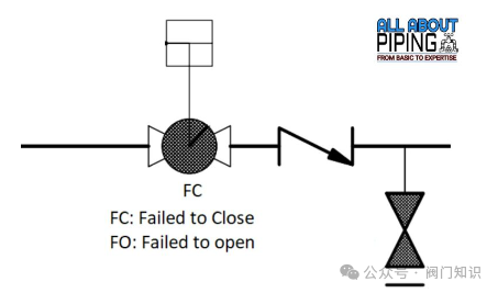
XV is a type of control valve that controls fluid flow. Typically, XV indicates a switch-type control valve. This means it either allows fluid to flow through it or completely stops it.
Usually, this type of control valve does not have any bypass valve as an auxiliary configuration. The XV valve always selects one of the following two operating methods:
-
Fail Close (FC):
This is usually displayed below the valve symbol in P&ID. Fail Close indicates the valve’s function, indicating that if the valve fails, it will stop the process fluid from flowing.
-
Fail Open (FO):
Conversely, FO below the control valve symbol indicates that if a failure occurs, it will remain open.
FC or FO can be selected based on the process requirements.
Pressure Control Valve (PV)
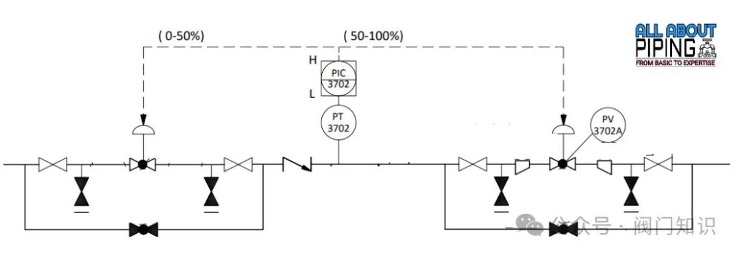
As the name suggests, a pressure control valve or PV is a valve commonly used to regulate and control fluid pressure in a system. The main function of the valve is to maintain a consistent pressure level within a specific range, regardless of changes in upstream or downstream pressure.
The operation of the pressure control valve involves opening and closing based on pressure changes, which helps regulate the fluid flow through the system. If the pressure exceeds the set point, the valve opens to allow fluid to escape and reduce pressure. Conversely, if the pressure drops below the set point, the valve closes to prevent fluid from escaping and increase pressure.
As shown in the figure above, the pressure control valve is connected to a pressure transmitter in the pipeline, which sends indications to the controller to operate the valve at the desired percentage of opening to maintain process pressure.
Note: Generally, the pressure transmitter and the pressure control valve or PV’s identification number are always the same for easy identification and adjustment of the system.
Flow Control Valve (FV)
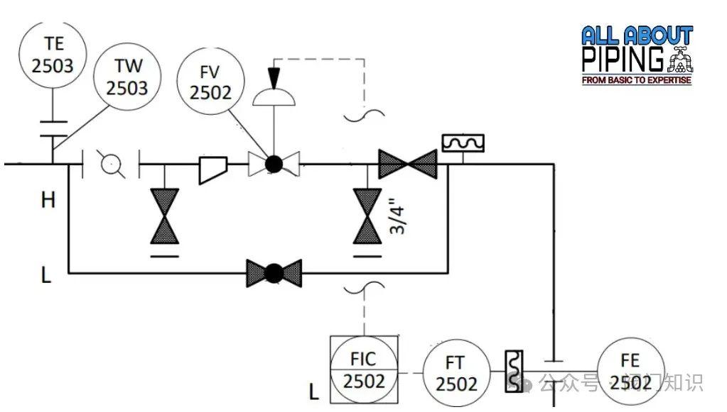
A flow control valve or FV is a valve that helps to regulate and control the flow rate of fluids in a system. Its working principle is to change the size of the valve opening to maintain a consistent flow rate within a specific range, regardless of what happens upstream or downstream.
The flow control valve adjusts the position of the valve plug from the flow meter (as shown in the figure above) to maintain the desired flow rate. In a manual flow control valve, the operator adjusts the position of the valve plug to control the flow.
If the fluid flow rate exceeds the predetermined level, the stem lowers the valve plug to reduce the opening size and decrease the flow rate. Conversely, if the flow rate drops below the set value, the stem raises the valve plug to increase the opening size, allowing more fluid to pass through.
Temperature Control Valve (TV)
A temperature control valve or TV is a valve used to regulate and control the temperature of fluids in a system. Its main function is to maintain a constant temperature within a specified range, regardless of changes in upstream or downstream conditions.
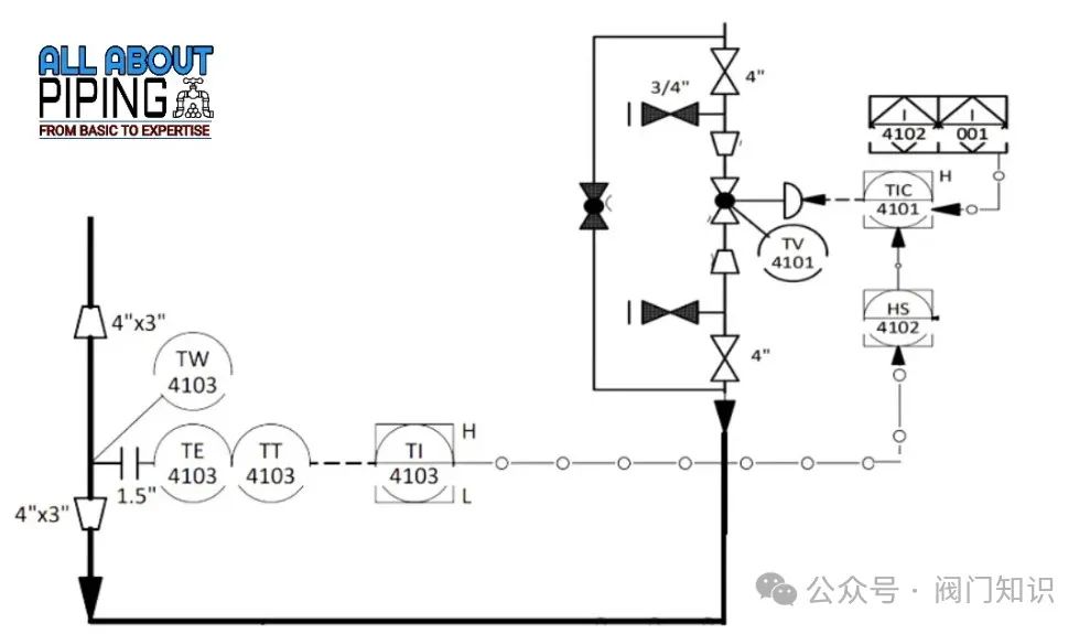
Temperature control valves are typically installed in pipelines or containers within processing systems and are connected to temperature sensors that monitor the temperature of the fluid or processing system. If the temperature is above or below the desired set point, the valve will adjust the flow of hot or cold fluid to maintain the desired temperature range.
In an automatic temperature control system, the valve is controlled by a temperature controller that receives input from the temperature sensor and adjusts the valve accordingly. The controller can be programmed to maintain a specific temperature range and can also be configured to provide alarms or shut down the process when the temperature deviates too far from the desired set point.
The temperature control valve is connected to temperature elements or thermocouple sleeves to detect temperature and send corresponding signals to operate the control valve.
Level Control Valve (LV)
A level control valve or LV is a device used to maintain a consistent liquid level in a tank or container. Its working principle is to regulate the flow of liquid entering and exiting the tank based on changes in the liquid level. This valve ensures that the level remains within a specific range, helping to prevent overflow, underflow, or other issues.
Level control valves are typically installed in pipelines or containers connected to tanks. They are connected to a level sensor that monitors the liquid level in the tank. When the level rises above or falls below the desired set point, the level control valve will adjust the liquid flow accordingly.
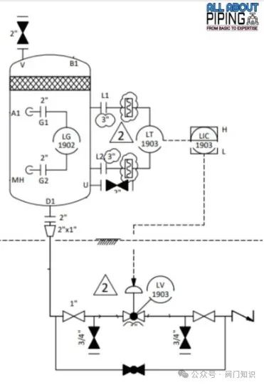
For example, if the liquid level rises above the desired set point, the valve will reduce the flow of liquid entering the tank to lower the level. Conversely, if the level drops below the desired set point, the valve will increase the flow of liquid entering the tank to raise the level.
As shown in the figure, the level control valve or LV is connected to a level transmitter that communicates with the valve to operate and control the flow.
Manual Control Valve (HV)
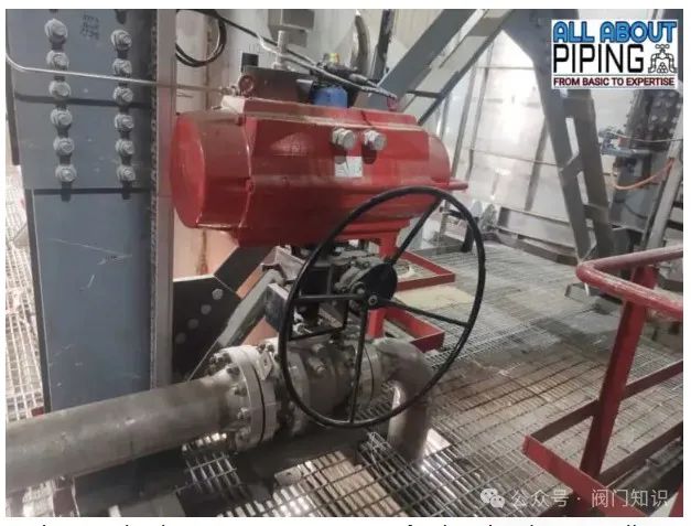
A manual control valve or HV is a valve that is manually controlled via a handle or lever. They are typically used in applications where manual control is required or preferred, especially in low-pressure or small-scale systems.
The handle or lever on the manual control valve is directly connected to the stem, which moves the valve plug to regulate the flow of fluid or gas through the valve. Turning the handle clockwise or counterclockwise adjusts the position of the valve element, thereby regulating the flow of fluid or gas.
These valves can be used to control the flow, pressure, or temperature of fluids or gases in various industrial processes, such as in heating and cooling systems, chemical processing facilities, and water treatment plants.
One advantage of manual control valves is their simplicity and ease of use. They do not require any external power source or complex control systems, making them an economical choice for many applications. Additionally, manual control allows for quick adjustments and immediate responses to changes in process conditions.
However, manual control valves have some limitations. They require human intervention to operate, which can be time-consuming and labor-intensive in large-scale systems. Furthermore, they may not be as precise or accurate as automatic control valves, which can lead to fluctuations or inconsistencies in the process.
Remote Operated Shut-Off Valve (ROSOV)
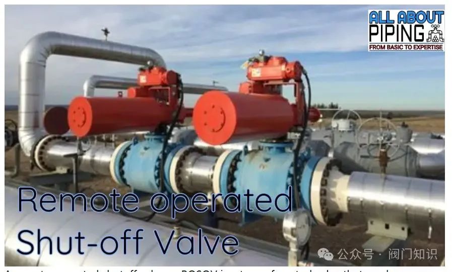
A remote-operated shut-off valve or ROSOV is a control valve that can be remotely controlled via electronic devices or computers. These valves are used in various industrial settings, including oil and gas pipelines, water treatment facilities, and chemical plants. They are typically installed in hard-to-reach or hazardous locations, such as deep underground or offshore.
In emergencies or as part of routine maintenance, the valve can be shut off remotely to prevent further damage or hazardous situations. This feature reduces the need for workers to physically contact the valve, minimizing the risk of accidents or injuries. Therefore, remote-operated shut-off valves are crucial for safety in industrial environments.
In summary, remote-operated shut-off valves are an important safety measure in many industries, protecting workers and the environment while preventing accidents.
Selection of Control Valves
When selecting control valves, the following criteria should be considered:
-
Type of Valve:
The type of valve should be selected based on application requirements, such as flow rate, pressure drop, and fluid characteristics.
-
Size of Valve:
The size of the valve should match the process flow and pipeline size to avoid issues such as high pressure drop or inefficiency.
-
Material of Valve:
The materials used for the valve should be compatible with the process fluid and operating conditions, such as temperature, pressure, and corrosion resistance.
-
Flow Characteristics:
Control valves have different flow characteristics, such as linear, equal percentage, and quick opening. The selected flow characteristic should meet the required control response and process requirements.
-
Type of Actuator:
Depending on the process requirements and available power sources, actuators can be pneumatic, electric, or hydraulic.
-
Maintenance Requirements:
Consideration should be given to the maintenance requirements of the valve, such as accessibility, repair, and parts replacement.
-
Cost:
The costs of the valve and related equipment, such as actuators and positioners, should be considered. The total cost of ownership over the valve’s lifecycle should also be taken into account.
By carefully considering these criteria, you can select the right control valve for your process control system and ensure optimal performance and efficiency.
Conclusion
In various industrial processes, control valves are essential components for regulating fluid flow, pressure, and temperature. They are crucial in systems such as oil and gas production, chemical processing, and water treatment.
Selecting the appropriate type of control valve based on application and specific control requirements is vital. The correct selection, installation, and maintenance of control valves are essential for their optimal performance and lifespan.
Technological advancements have led to the development of more precise control valves that offer higher accuracy, reliability, and efficiency. Given their critical role in process control, control valves will continue to play an important role in numerous industries.
Source: Valve Knowledge WeChat Official Account
Disclaimer: If the videos, images, and text used in this article involve copyright issues, please inform us immediately, and we will confirm the copyright based on the proof materials you provide and pay remuneration according to national standards or delete the content immediately!010-88379790 ext. 612
Business Cooperation: 18240442679 Manager Fu