1. Introduction to Proteus VSM Simulation Models
During the use of Proteus to simulate microcontroller systems, it is often difficult to find the required components, necessitating custom development. A key feature of Proteus VSM is its extensibility through DLL-based component models. These models are divided into two categories: Electrical Models and Graphical Models. The Electrical Model implements the electrical characteristics of components, receiving and outputting data according to specified timing; the Graphical Model facilitates user interaction during simulation, such as displaying on an LCD. A component can implement only the Electrical Model, or both the Electrical and Graphical Models.
Proteus provides several C++ abstract class interfaces for VSM models, which users need to implement in the DLL when creating components. The communication principle between the VSM model and the Proteus system is illustrated in the figure below:
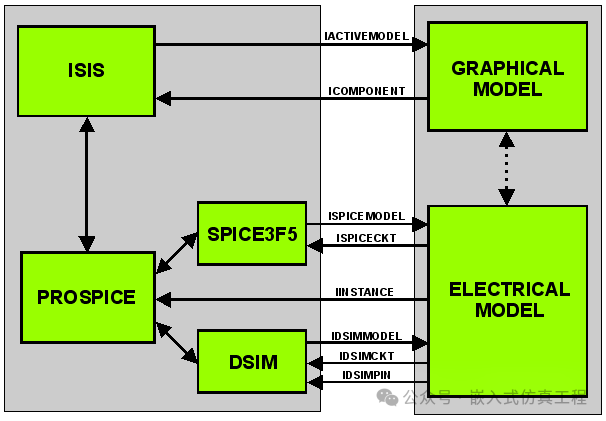
Graphical Model Interface Abstract Classes:
ICOMPONENT – An active component object within ISIS, providing drawing and user interaction services for the VSM model on the schematic.
IACTIVEMODEL – The VSM graphical model implemented by the user must inherit from this class and implement the corresponding drawing and keyboard/mouse event handling.
Electrical Model Interface Abstract Classes:
IINSTANCE – A PROSPICE simulation primitive model that provides access to properties, simulation nodes, and data pins for the VSM model, allowing the model to issue warnings and error messages through the simulation log.
ISPICECKT (Analog) – An analog component owned by SPICE, providing services to access, create, and delete nodes, allocate space on a sparse matrix, and allow the model to force simulation time points to occur and suspend simulation at given times.
ISPICEMODEL (Analog) – The VSM analog component implemented by the user must inherit from this class and implement the corresponding data loading and processing at completion time.
IDSIMCKT (Digital) – A digital component owned by DSIM, providing services to access variables in the digital system, create callback functions, and suspend simulation.
IDSIMMODEL (Digital) – The VSM digital component implemented by the user must inherit from this class and implement the corresponding pin state change judgment and callback event handling.
IDSIMPIN (Digital) – Pins of the digital component, providing services to detect pin states and create output transaction events.
IDBUSPIN (Digital) – The data or address bus of the digital component, providing services to detect bus states and create bus output transaction events.
IMIXEDMODEL (Mixed) – Inherits both ISPICEMODEL and IDSIMMODEL, indicating that the component has both analog and digital characteristics.
To allow Proteus to access member functions in the user model, an instance of the user model must be created. This cannot be achieved through class interfaces but must be done by exporting several C functions from the DLL, which must be implemented in the user model to construct and destruct the user model instance.
(1) Constructing and destructing graphical model instances:
IACTIVEMODEL *createactivemodel (CHAR *device, ILICENCESERVER *ils)
VOID deleteactivemodel (IACTIVEMODEL *model)
(2) Constructing and destructing analog electrical model instances:
ISPICEMODEL *createspicemodel (CHAR *device, ILICENCESERVER *ils)
VOID deletespicemodel (ISPICEMODEL *model)
(3) Constructing and destructing digital electrical model instances:
IDSIMMODEL *createdsimmodel (CHAR *device, ILICENCESERVER *ils)
VOID deletedsimmodel (IDSIMMODEL *model)
(4) Constructing and destructing mixed electrical model instances:
IMIXEDMODEL *createmixedmodel (CHAR *device, ILICENCESERVER *ils)
VOID deletemixedmodel (IDSIMMODEL *model)
2. Development Process of Proteus VSM Simulation Models
1. Draw component graphics, pins, and related symbols.
2. Create the component and set its properties.
3. Write the component in C++, implementing the electrical and graphical models, and compile to generate the DLL.
4. Build the circuit simulation test.
3. Example of VSM Model Development
Below, we will detail the development process using the TG19264A dot matrix LCD component as an example.
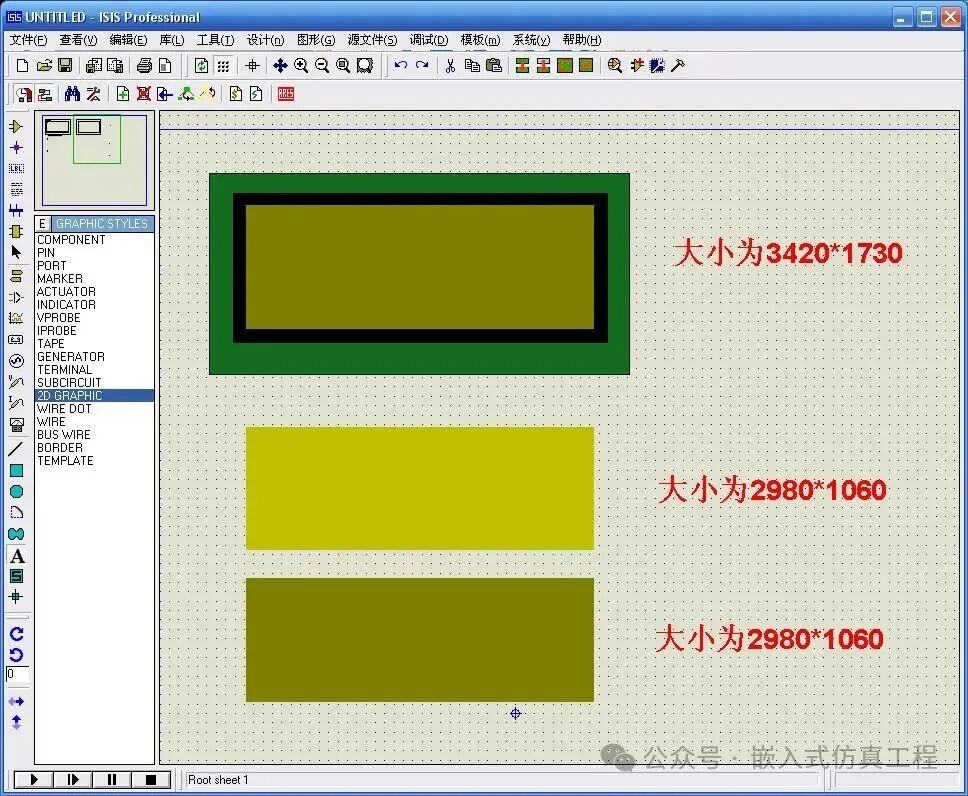
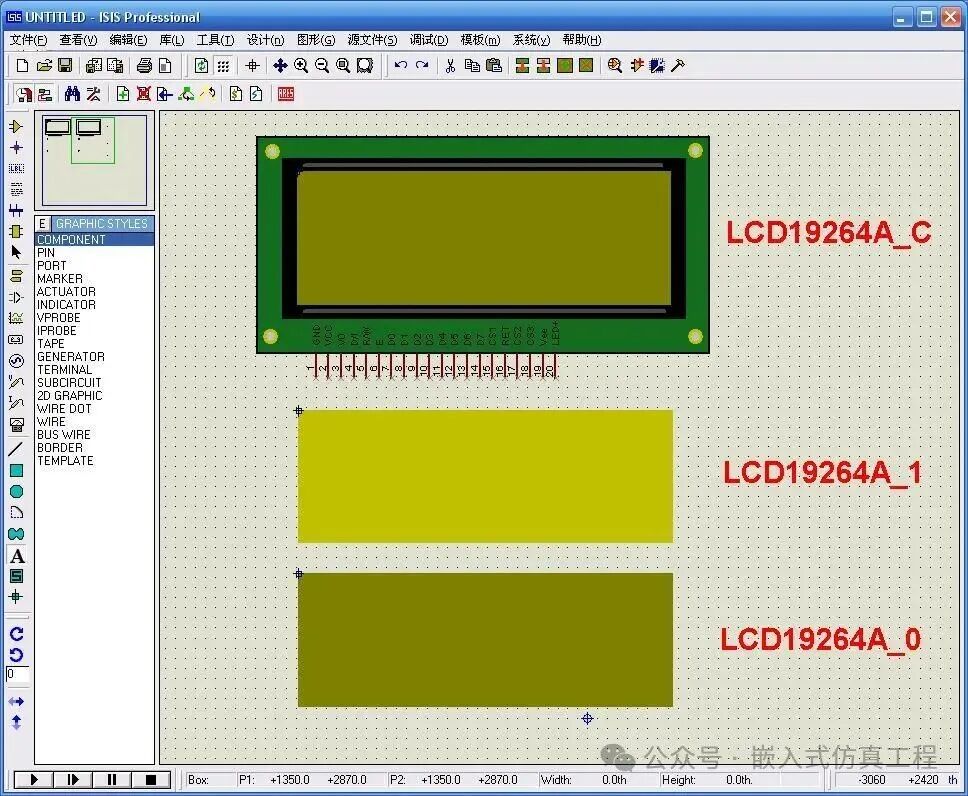
1. Open Proteus, select the menu View >> Snap 10th, and choose the 2D graphics box from the left drawing toolbar to draw the three shapes as shown in the figure.
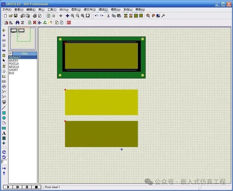
2. Select the 2D graphics line, draw two straight lines, set the width to 36th, and color to gray. Select 2D graphics circle to draw four mounting holes at the corners. Use Markers for component origin to draw the symbol origin for the three shapes (the red parts in the figure).
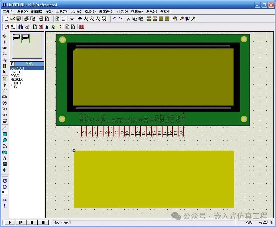
3. Select Device pin, rotate it 90 degrees clockwise, and place 20 pins as shown in the figure. Set the electrical types for GND, VCC, V0, Vee, LED+ to PP-Power Pin, and for D/I, R/W, E, CS1, RET, CS2, CS3 to IP-Input, and for D0~D7 to IO-Bidirectional.
4. Right-click to drag out the selection box to select the first symbol, choose the menu Library >> Create Symbol, name it LCD19264A_C, and confirm. Similarly, name the second and third symbols as LCD19264A_1 and LCD19264A_0 respectively. When the user calls drawsymbol (-1), it will draw LCD19264A_C; calling drawsymbol (1) will draw LCD19264A_1; calling drawsymbol (0) will draw LCD19264A_0.
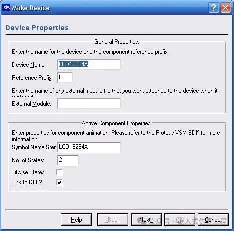
5. Right-click to drag out the selection box to select the symbol LCD19264A_C, choose the menu Library >> Create Component, set Device Properties as shown in the figure, and click Next >. Skip the package settings and click Next >. Set the component properties as shown in the figure, and click Next >. Select the datasheet (optional), and click Next >. Select the device library and click OK.
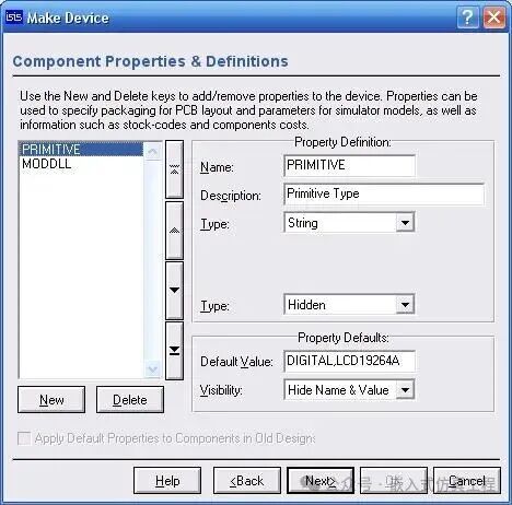
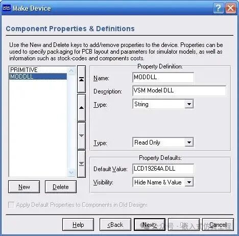
6. Open VC, create a new project, select Win32 Dynamic-Link Library, name the project, and establish an empty DLL project. Copy VSM.HPP from the INCLUDE folder of the Proteus installation directory to the current project directory, create files LCD19264A.H and LCD19264A.CPP, and write the following code.
/*****************************************************************
* File: LCD19264A.H
* Description: The following features are not supported
* (1) Display switch control is not supported
* (2) Setting the starting line for display is not supported
*****************************************************************/
#include “vsm.hpp”
//LCD Constants
#define LCD_BLK_NUM 3 //lcd block number
#define LCD_BLK_LEN 64 //lcd block length
#define LCD_LINE_NUM 8 //lcd line number
#define LCD_LENGTH (LCD_BLK_LEN*LCD_BLK_NUM) //lcd length
#define LCD_WIDTH 64 //lcd width
#define BLANK_WIDTH 50 //the width of blank
#define SYM_LINEWIDTH 28 //the width of symbol line
//LCD Command Masks
#define CMD_MASK 0xc0
//LCD Commands
#define DISP_ONOFF 0x00 //Switch backlight
#define SET_STARTLINE 0xc0 //Set starting line
#define SET_XADDRESS 0x80 //Set X address
#define SET_YADDRESS 0x40 //Set Y address
//Delay Constants
#define DELAY_1s 1000000000000
#define DELAY_1ms 1000000000
#define DELAY_1us 1000000
#define DELAY_1ns 1000
#define DELAY_1ps 1
/*
LCD components have both digital electrical characteristics and drawing characteristics, so they must inherit from IACTIVEMODEL and IDSIMMODEL
*/
class LCD19264A : public IACTIVEMODEL, public IDSIMMODEL
{
public:
/* Electrical Model Member Functions */
//Digital circuits always return TRUE
INT isdigital (CHAR *pinname);
//Called when creating the model instance, for initialization
VOID setup (IINSTANCE *inst, IDSIMCKT *dsim);
//Simulation run mode control, called at the start of each frame in interactive simulation
VOID runctrl (RUNMODES mode);
//Called when the user changes the state of keys, etc., during interactive simulation
VOID actuate (REALTIME time, ACTIVESTATE newstate);
//Called at the end of each frame during interactive simulation, communicates with the graphical model by passing ACTIVEDATA data, thus calling animate() for drawing
BOOL indicate (REALTIME time, ACTIVEDATA *data);
//Called when pin states change, mainly used to handle data input and output
VOID simulate (ABSTIME time, DSIMMODES mode);
//Callback function that can be set to be called at a given time via setcallback()
VOID callback (ABSTIME time, EVENTID eventid);
/* Graphical Model Member Functions */
//Called when creating the model instance, for initialization
VOID initialize (ICOMPONENT *cpt);
//Called by PROSPICE, returns the analog electrical model
ISPICEMODEL *getspicemodel (CHAR *device);
//Called by PROSPICE, returns the digital electrical model
IDSIMMODEL *getdsimmodel (CHAR *device);
//Called when the schematic needs to be redrawn
VOID plot (ACTIVESTATE state);
//Called when the corresponding electrical model generates active events, commonly used to update graphics
VOID animate (INT element, ACTIVEDATA *newstate);
//Used to handle keyboard and mouse events
BOOL actuate (WORD key, INT x, INT y, DWORD flags);
private:
IINSTANCE *instance; //PROSPICE simulation primitive model
IDSIMCKT *ckt; //DSIM’s digital component
ICOMPONENT *component; //An active component object within ISIS
//Pin Definitions
IDSIMPIN *di; //D/I
IDSIMPIN *rw; //R/W
IDSIMPIN *en; //E
IDSIMPIN *cs1; //CS1
IDSIMPIN *cs2; //CS2
IDSIMPIN *cs3; //CS3
IDSIMPIN *d[8]; //D0~D7
IBUSPIN *databus; //D[0..7]
//LCD Parameters
BYTE x_addr; //X address (see manual)
BYTE y_addr; //Y address (see manual)
BYTE status; //Status (see manual)
BYTE cur_blk; //Current block number (total of 3 blocks, see manual)
BYTE DDRAM[LCD_BLK_NUM][LCD_BLK_LEN*LCD_WIDTH/8]; //LCD display RAM
BOOL new_flag; //New data arrival flag
//Display Parameters
BOX lcdarea; //LCD display area
float pix_width, pix_height; //Width and height of the rectangle corresponding to each pixel
};
/*****************************************************************
* File: LCD19264A.CPP
* Description: The following features are not supported
* (1) Display switch control is not supported
* (2) Setting the starting line for display is not supported
*****************************************************************/
#include
#include “LCD19264A.h”
//—————————————————————————-
//Implementation of the electrical model
//Constructing the digital electrical model instance
extern “C” IDSIMMODEL __declspec(dllexport) * createdsimmodel (CHAR *device, ILICENCESERVER *ils)
{
//Authorization
ils->authorize(0x88888888, 0x69); //Version 6.9
return new LCD19264A; //Create model instance
}
//Destructing the digital electrical model instance
extern “C” VOID __declspec(dllexport) deletedsimmodel (IDSIMMODEL *model)
{
delete (LCD19264A *)model; //Delete model instance
}
//Digital circuits always return TRUE
INT LCD19264A::isdigital (CHAR *pinname)
{
return 1;
}
//Called when creating the model instance, for initialization
VOID LCD19264A::setup (IINSTANCE *inst, IDSIMCKT *dsim)
{
instance = inst; //PROSPICE simulation primitive model
ckt = dsim; //DSIM’s digital component
//Get pins
di = instance->getdsimpin(“D/I,d/i”, true);
di->setstate(FLT); //FLOAT
rw = instance->getdsimpin(“R/W,r/w”, true);
rw->setstate(FLT);
en = instance->getdsimpin(“E,e”, true);
en->setstate(FLT);
cs1 = instance->getdsimpin(“CS1,cs1”, true);
cs1->setstate(FLT);
cs2 = instance->getdsimpin(“CS2,cs2”, true);
cs2->setstate(FLT);
cs3 = instance->getdsimpin(“CS3,cs3”, true);
cs3->setstate(FLT);
d[0] = instance->getdsimpin(“D0,d0”, true);
d[0]->setstate(FLT);
d[1] = instance->getdsimpin(“D1,d1”, true);
d[1]->setstate(FLT);
d[2] = instance->getdsimpin(“D2,d2”, true);
d[2]->setstate(FLT);
d[3] = instance->getdsimpin(“D3,d3”, true);
d[3]->setstate(FLT);
d[4] = instance->getdsimpin(“D4,d4”, true);
d[4]->setstate(FLT);
d[5] = instance->getdsimpin(“D5,d5”, true);
d[5]->setstate(FLT);
d[6] = instance->getdsimpin(“D6,d6”, true);
d[6]->setstate(FLT);
d[7] = instance->getdsimpin(“D7,d7”, true);
d[7]->setstate(FLT);
//For convenience, map D0~D7 to an 8-bit bus
databus = instance->getbuspin(“LCD_DBUS”, d, 8);
databus->settiming(100,100,100); //Set time delay
databus->setstates(SHI,SLO,FLT); //Set bus logic to [1,0, tri-state] driving state
//lcd model
x_addr = 0; //X address (see manual)
y_addr = 0; //Y address (see manual)
status = 0; //Status (see manual)
new_flag = TRUE; //New data arrival flag
}
//Simulation run mode control, called at the start of each frame in interactive simulation
VOID LCD19264A::runctrl (RUNMODES mode)
{
}
//Called when the user changes the state of keys, etc., during interactive simulation
VOID LCD19264A::actuate (REALTIME time, ACTIVESTATE newstate)
{
}
//Called at the end of each frame during interactive simulation, communicates with the graphical model by passing ACTIVEDATA data, thus calling animate() for drawing
BOOL LCD19264A::indicate (REALTIME time, ACTIVEDATA *data)
{
if(new_flag){
//New data has arrived
data->type = ADT_REAL; //call back animate() to refresh lcd
data->realval = (float)time*DSIMTICK;
}
return TRUE;
}
//Called when pin states change, mainly used to handle data input and output
VOID LCD19264A::simulate (ABSTIME time, DSIMMODES mode)
{
BYTE data;
if(en->isnegedge()){
//E’s falling edge arrives
if((rw->istate()==SLO)||(rw->istate()==WLO)){
//R/W low indicates write
//Read block selection
if((cs1->istate()==SLO)||(cs1->istate()==WLO))
cur_blk = 0;
else if((cs2->istate()==SLO)||(cs2->istate()==WLO))
cur_blk = 1;
else if((cs3->istate()==SLO)||(cs3->istate()==WLO))
cur_blk = 2;
else
return; //not select block
data = (BYTE)databus->getbusvalue(); //Read data
if((di->istate()==SHI)||(di->istate()==WHI)){
//D/I high indicates data
DDRAM[cur_blk][x_addr*LCD_BLK_LEN+y_addr] = data; //Write data
new_flag = TRUE; //New data arrival flag
y_addr = ((y_addr+1)%LCD_BLK_LEN); //y address auto increment
if(y_addr==0)
x_addr = ((x_addr+1)%LCD_LINE_NUM); //Auto line feed
}else{
//D/I low indicates command
switch(data&CMD_MASK)
{
case DISP_ONOFF:
//Switch backlight
break;
case SET_STARTLINE:
//Set starting line
break;
case SET_XADDRESS:
//Set X address
x_addr = (data&0x07); //bit2~bit0
break;
case SET_YADDRESS:
//Set Y address
y_addr = (data&0x3f); //bit5~bit0
break;
default:
break;
}
}else if(en->isposedge() && ((rw->istate()==SHI)||(rw->istate()==WHI))){
//E’s rising edge arrives, R/W high indicates read
if((di->istate()==SHI)||(di->istate()==WHI)){
//D/I high indicates data
//Read block selection
if((cs1->istate()==SLO)||(cs1->istate()==WLO))
cur_blk = 0;
else if((cs2->istate()==SLO)||(cs2->istate()==WLO))
cur_blk = 1;
else if((cs3->istate()==SLO)||(cs3->istate()==WLO))
cur_blk = 2;
else
return; //not select block
data = DDRAM[cur_blk][x_addr*LCD_BLK_LEN+y_addr]; //Read data
databus->drivebusvalue(time, data); //Output data
y_addr = ((y_addr+1)%LCD_BLK_LEN); //y address auto increment
if(y_addr==0)
x_addr = ((x_addr+1)%LCD_LINE_NUM); //Auto line feed
}else{
//D/I low indicates command
databus->drivebusvalue(time, status); //Output status
}
}
}//End of LCD19264A class
Welcome to follow (operation reference article: Send a message to the public account), click the blue text at the top “
Embedded Simulation Project
” or long press to identify the QR code to follow