EMC Considerations in PCB Design

EMC Considerations in PCB Design

As the saying goes, to shoot a person, first shoot the horse; to capture a thief, first capture the king. The best way to solve EMC issues is to establish EMC rules for the PCBA. The following are my personal insights for reference! 1. Layer Configuration 1.1 Is the number of layers set reasonably? 1.1.1 … Read more

Why Are High-Speed Signal Traces Curved on PCBA Boards?

Why Are High-Speed Signal Traces Curved on PCBA Boards?

Analysis of the Reasons for Curved High-Speed Signal Traces on PCBA Boards 1. The Special Nature of High-Speed Signals and Routing Requirements In PCBA (Printed Circuit Board Assembly) design, high-speed signals typically refer to signals with frequencies above 100MHz or transmission rates exceeding 1Gbps, such as PCIe, DDR, USB 3.0, etc. The transmission of these … Read more

Challenges and Future Evolution of Optical Module Technology on PCBs

Challenges and Future Evolution of Optical Module Technology on PCBs

Challenges and Future Evolution of Optical Module Technology on PCBs As the core interconnection unit of computing infrastructure such as data centers and 5G communications, optical modules have undergone a technological evolution from 100G to 400G, 800G, and even 1.6T, which has imposed comprehensive technical reconstruction requirements on the PCBs (Printed Circuit Boards) that carry … Read more

PCB Design Specifications: VGA Design Guidelines

PCB Design Specifications: VGA Design Guidelines

Documenting work, sharing experiences, and open-sourcing! Accelerate progress! Contributing to continuous improvement Dedicated to ensuring that every design is theoretically supported. Mark it as a favorite, mark it as a favorite. Today we tackle VGA. 1. When there are no special requirements for VGA signals, use single-ended connections. (R, G, B) 75Ω; Hsync and Vsync … Read more

Understanding in One Minute: The Time Bomb of Design Flaws – Hidden Causes of PCB Failure

Understanding in One Minute: The Time Bomb of Design Flaws - Hidden Causes of PCB Failure

Click to receive a free sample coupon~ In the field of electronic manufacturing, PCBs serve as the “nervous system” of electronic products, and the quality of their design directly determines the performance and reliability of the products. However, some seemingly reasonable PCB designs may hide fatal flaws, becoming time bombs for product failure. This article … Read more

High-Frequency Circuit Board Manufacturer Recommendations

High-Frequency Circuit Board Manufacturer Recommendations

In today’s rapidly advancing electronic technology, high-frequency circuit boards have become core components in fields such as 5G communication, satellite radar, and high-speed data processing. These areas have extremely high requirements for signal integrity and low-loss transmission, making the choice of a reliable manufacturer crucial. This high-frequency circuit board recommendation consultation will systematically introduce the … Read more

Eight-Layer PCB Fabrication | High-Speed Signal Integrity and Impedance Control

Eight-Layer PCB Fabrication | High-Speed Signal Integrity and Impedance Control

Eight-Layer PCB Fabrication | High-Speed Signal Integrity and Impedance Control In high-speed digital circuits and RF applications, signal integrity and impedance control are critical factors determining device performance. The eight-layer PCB, with its multilayer stack design, has become the preferred solution for addressing high-frequency signal interference and enhancing transmission efficiency. As a professional manufacturer with … Read more

Why Connect a Resistor and Capacitor Between PCB GND and Chassis GND?

Why Connect a Resistor and Capacitor Between PCB GND and Chassis GND?

The chassis is metallic, with a screw hole in the middle that connects to the ground. Here, a 1M resistor is connected in parallel with a 1nF capacitor to the circuit board ground. What are the benefits of this setup?In metal chassis devices, the PCB GND (signal ground) is connected to the chassis GND (enclosure … Read more

FPGA Hardware Development – DDR Design

FPGA Hardware Development - DDR Design

1. Hardware Circuit Design (Basic Assurance) Power Supply and Ripple Control The core power supply (e.g., 1.2V for DDR4) should be independently powered, paired with a capacitor array of 10μF + 0.1μF, with ripple control within ±5%; Termination resistors (ODT) should be placed close to the DDR chips, with matched impedance (typically 50Ω/60Ω) to reduce … Read more

Back Drilling Process in PCB Manufacturing: What Are Its Basic Principles and Objectives? How Does It Differ from Traditional Through-Hole Drilling?

Back Drilling Process in PCB Manufacturing: What Are Its Basic Principles and Objectives? How Does It Differ from Traditional Through-Hole Drilling?

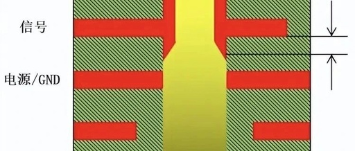
Back drilling process in PCB manufacturing: A key manufacturing technology for enhancing the integrity of high-speed signals. In the fields of high-speed digital circuits and RF microwave, the PCB back drilling process can significantly improve signal integrity by removing excess via stubs, making it an indispensable technology in modern electronic manufacturing. In modern electronic devices, … Read more