The chassis is metallic, with a screw hole in the middle that connects to the ground. Here, a 1M resistor is connected in parallel with a 1nF capacitor to the circuit board ground. What are the benefits of this setup?In metal chassis devices, the PCB GND (signal ground) is connected to the chassis GND (enclosure ground) throughparallel connection of a resistor and capacitor (referred to as RC grounding), which is a classic design that balanceselectrical safety,EMC performance, andsignal integrity. What are the advantages of this approach?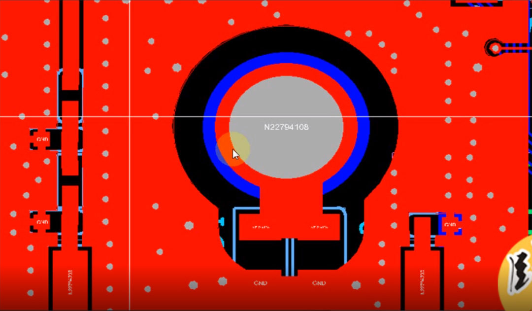
Basic Principles
1. Function of the Capacitor: High-Frequency Noise Low-Impedance Discharge
-
High-Frequency Noise Bypass:
The metal chassis is prone to coupling external electromagnetic interference (such as RF noise and switching power supply noise). The capacitor (typically 1nF to 100nF) provides a low-impedance path for high-frequency noise, directing the interference into the chassis (Faraday cage effect), preventing it from affecting the internal circuit;
-
Suppressing EMI Radiation:
The capacitor can reduce the high-frequency noise from the circuit board leaking out through radiation or conduction, helping to pass EMC tests;
2. Function of the Resistor: Low-Frequency Isolation and Safety Current Limiting
-
Blocking Ground Loop Currents:
If the PCB GND is directly shorted to the chassis, the potential difference between different grounding points can create ground loop currents (such as 50Hz power frequency interference). The resistor (typically 1MΩ to 10MΩ) can block low-frequency loops, avoiding common-mode noise.
-
Safety Protection:
The resistor limits leakage current (such as leakage current from AC mains devices), preventing electric shock risks and meeting safety standards (such as IEC 60950 requiring leakage current < 0.1mA).
-
If there is static electricity or high voltage outside, it can also effectively reduce the current, preventing damage to the chips inside the circuit.
3. Synergistic Effect of RC Parallel Connection
Avoid low-frequency noise introduced by ground loops (such as the “hum” in audio equipment), while not obstructing the return path of high-frequency signals. The capacitor is generally chosen to be 1nF to 100nF, and the resistor is typically 1MΩ to 10MΩ. The RC network should be as close as possible to the PCB grounding point, with short and thick capacitor leads, and the chassis grounding point should have low impedance (such as conductive foam).
-
At low frequencies: The resistor dominates (high impedance), blocking ground loops;
-
At high frequencies: The capacitor dominates (low impedance), discharging noise.
-
Balancing Safety and EMC: Avoids the risks of direct shorting while addressing EMI issues caused by complete floating ground.
Comparison with Other Grounding Solutions:
 Add Ecosmos Activity Manager to unlock 200+ free PCB schematics15G hardware data, semiconductor industry maps1000+ domestic alternative directories and other materialsYou can also join the industry exchange group for sharing cutting-edge information