The camera is so small, yet the data is so abundant, it must be using the MIPI interface. In the previous article, we learned about VGA timing, and now understanding MIPI is much easier.
MIPI is a digital protocol, so the focus is on how the DATA is encapsulated!
It can be seen that it is divided into long and short packets.
To thoroughly understand this, I will carefully analyze this timing process.
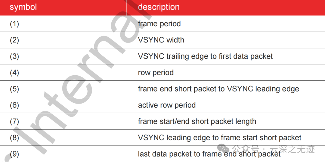
The document provides the duration of the timing.
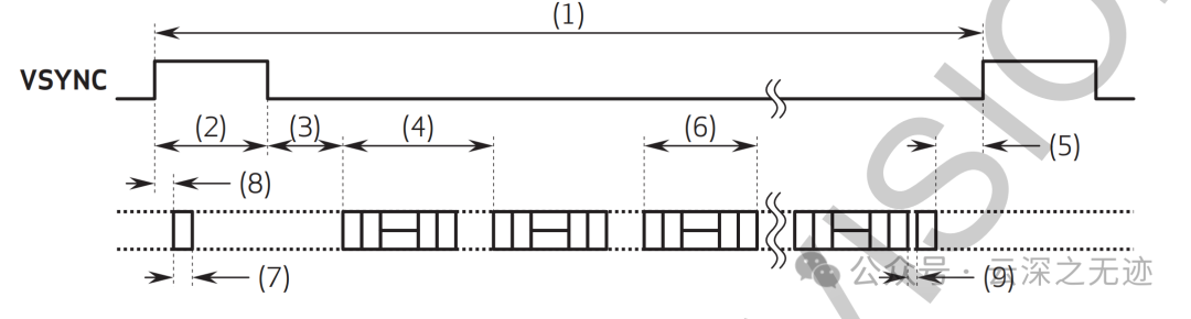
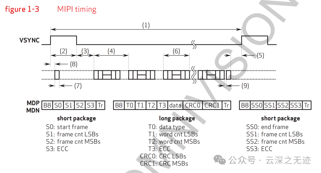
(1) Frame period: Refers to the time for a complete frame, usually the time required from the start to the end of an image frame. It can be seen as the time from one edge to the other.

There is this pin.
(2) VSYNC width: The width of the VSYNC signal, which is the duration of the vertical sync pulse. The time for one frame.
(3) VSYNC trailing edge to first data packet: The time interval from the trailing edge of the VSYNC signal to the start of the first data packet transmission. This is the time when the frame signal arrives, and then the image data actually starts to be transmitted.
(4) Row period: Refers to the time for transmitting each row of data.
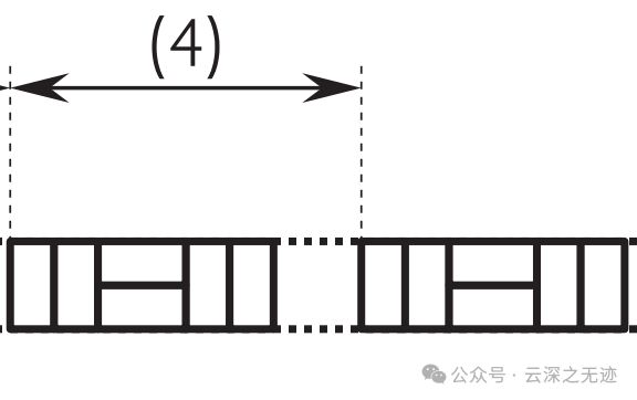
A grid like this represents one row of data.
(5) Frame end short packet to VSYNC leading edge: The time between the short packet at the end of the frame and the leading edge of the VSYNC signal.
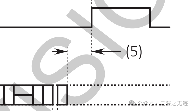
This is the time from when the data is finished to the next sync signal.
(6) Active row period: The period time for the rows of valid data transmission.
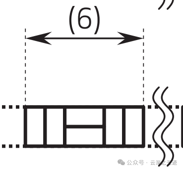
This is the actual data.
(7) Frame start/end short packet length: The length of the short packet at the start or end of the frame.
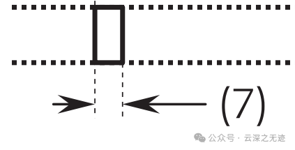
The short packet looks like this; the two grids should represent two short packets.
(8) VSYNC leading edge to frame start short packet: From the leading edge of the VSYNC signal to the frame start short packet.
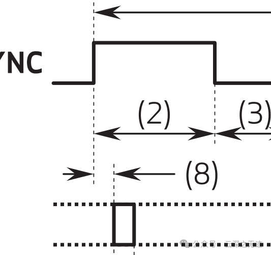
This is detailed down to the timing of the short packet.
(9) Last data packet to frame end short packet: The time interval from the last data packet to the frame end short packet.
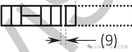
The time between one packet and another.
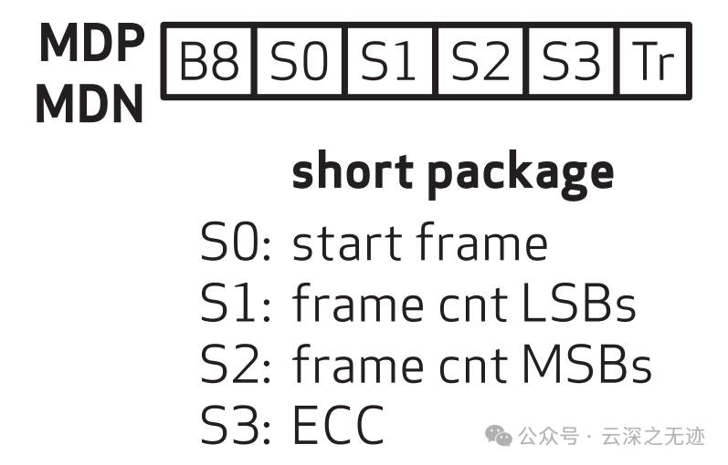
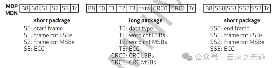
This is the appearance of a short packet.
Short packets include:
- S0: Start frame
- S1, S2: Frame count (low and high bits)
- S3: ECC (Error Checking Code)
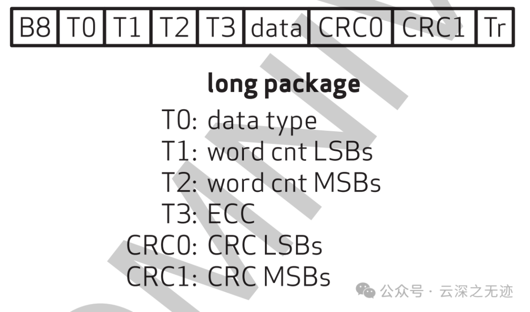
This is a long packet.
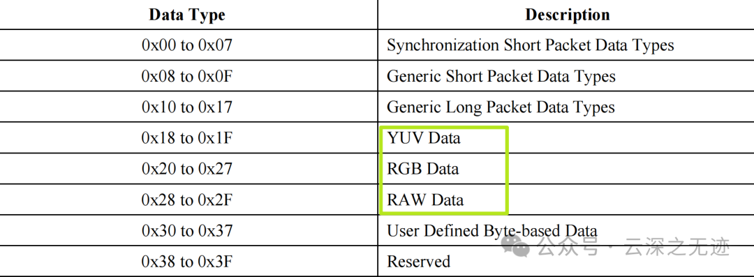
This is DT, the data type.
T3 and beyond are data packets.
- T0, T1, T2, T3: Data type, low word count, high word count, and ECC
- CRC0, CRC1: CRC values
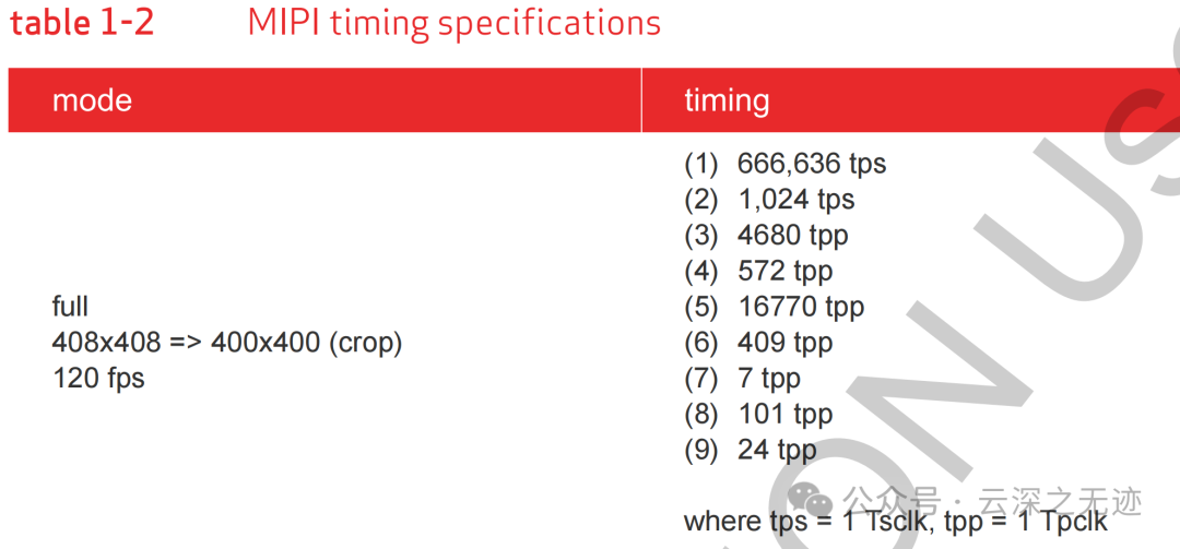
This is the first type of transmission, 400×400, followed by the timing of the time.
Each clock cycle (tps) and the number of pixels per clock cycle (tpp) are listed.
(1) Frame period: Refers to the time for a complete frame, usually the time required from the start to the end of an image frame.
(2) VSYNC width: The width of the VSYNC signal, which is the duration of the vertical sync pulse.
(3) VSYNC trailing edge to first data packet: The time interval from the trailing edge of the VSYNC signal to the start of the first data packet transmission.
(4) Row period: Refers to the time for transmitting each row of data.
(5) Frame end short packet to VSYNC leading edge: The time between the short packet at the end of the frame and the leading edge of the VSYNC signal.
(6) Active row period: The period time for the rows of valid data transmission.
(7) Frame start/end short packet length: The length of the short packet at the start or end of the frame.
(8) VSYNC leading edge to frame start short packet: From the leading edge of the VSYNC signal to the frame start short packet.
(9) Last data packet to frame end short packet: The time interval from the last data packet to the frame end short packet.
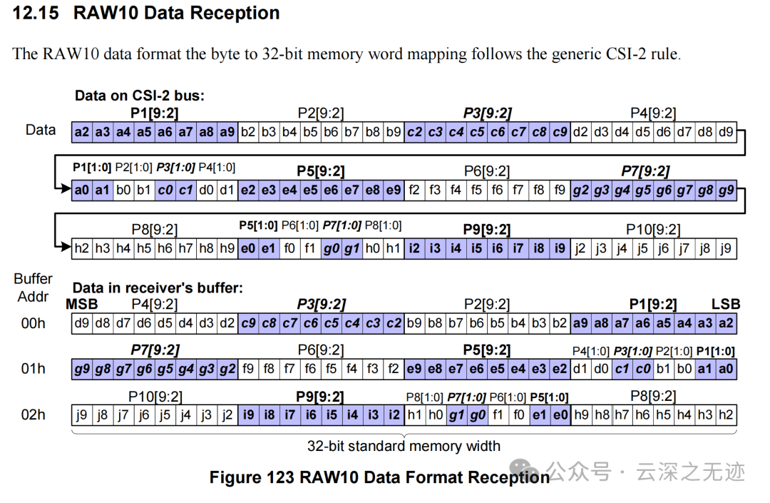
Let’s look at a proper RAW10 output format.
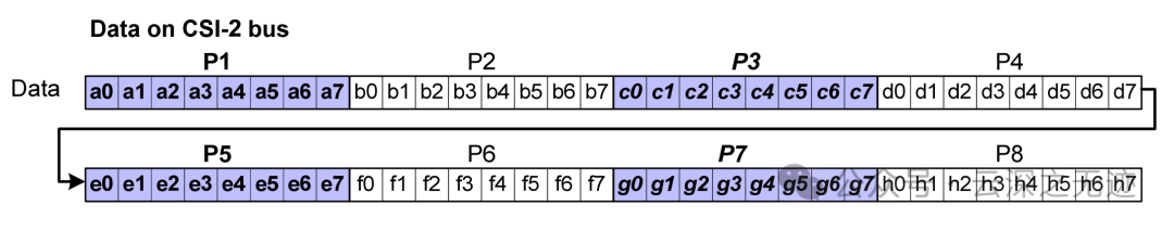
When the image sensor outputs RAW10 format data, the color information of each pixel is encoded in 10 bits (2 bytes), but since image sensors and data processors typically use an 8-bit memory structure, RAW10 data needs to be packed during transmission.
Each data unit: RAW10 data is processed in units of 10 bits. Each 10-bit data will be split and transmitted through multiple signal lines (such as P1, P2, P3, etc.).
12Bytes
8RAW is good, it fills up nicely.
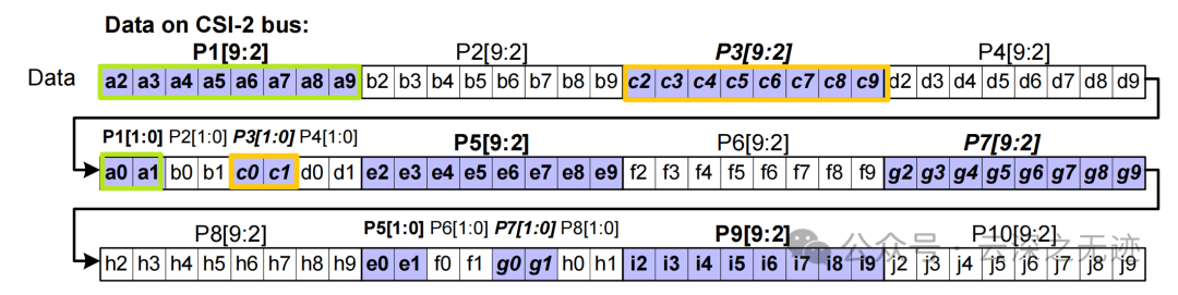
In the image, we can see how data starts from P1[9:2] (the 9th to 2nd bits of the P1 signal) and is transmitted through multiple data buses, such as P2[9:2], P3[9:2], etc., sequentially passing the high bits of the image data.The low bit data (P1[1:0], P2[1:0], etc.) is also transmitted through different data lines. Each data line has a total of 10 bits, where the first 8 bits are high bit data, and the last 2 bits are low bit data.
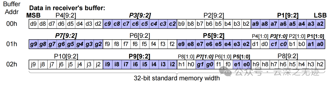
It’s sent out, but how is it stored?
32-bit wide memory: Since processors typically use 32-bit wide memory, each memory unit will accommodate multiple transmission data units. To accommodate the transmission of 10-bit data, these data are packed for storage in a 32-bit memory format.
It just fits, the last byte is used to store the low bits of each preceding byte.
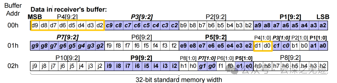
For example, P4[9:2] and P5[9:2] will be stored in the same 32-bit unit in the receiver’s memory. Specifically, the low bits of P4 and P5 will occupy different positions in the 32-bit memory word, allowing the receiver to process these data in parallel.The memory address starts from 00h and fills in the order of 32-bit words. This is a standard memory width, ensuring that the transmitted data is stored and processed in order.
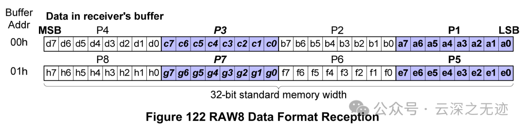
8 bits are no longer needed.
Initialization:
- Configure the MIPI interface parameters of the camera (such as resolution, frame rate, data format).
- Start the MIPI interface and enter LP mode.
Frame transmission:
- Send the frame start short data packet (Frame Start Packet).
- Sequentially send image data long data packets (Long Packet).
- Send the frame end short data packet (Frame End Packet).
Low power mode:
- Enter LP mode when there is no data transmission.
- Transmit control signals (such as VSYNC, HSYNC) through LP mode.
It’s not too complicated.