Hello everyone, I am Goat-kun.
In electronic circuit hardware development, if you want the circuit board system to operate normally, its signal quality must be flawless. Issues with signal quality can lead to signal recognition errors or reduced longevity, among other problems. Therefore, a qualified electronic hardware product must ensure signal integrity (SI).
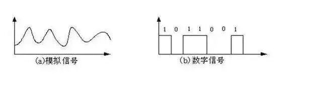
Signals can be categorized into two types: analog signals and digital signals. Analog signals vary continuously in both time and amplitude, while digital signals are discrete in time and typically have only two states: high and low.
Recently, while browsing the MPS Forum, I learned a lot of hardware insights, and many engineers are sharing valuable information and engaging in technical discussions. Interested friends can click the original text at the end to explore; it’s full of knowledge, and perhaps the issues that have troubled you for years can be resolved in the forum’s technical posts.
Let’s talk about the more prevalent digital signals.
Digital signals generally include power, clock, data, differential, serial communication, reset, and other signals that require quality assurance.
For example, for clock signals, we need to examine their edge monotonicity, actual frequency, frequency accuracy, and duty cycle. If the quality of the clock signal is compromised, such as the occurrence of a glitch, it may lead to incorrect level determination, treating the glitch as a valid clock pulse, which can cause the system to fail to operate reliably and stably.
So, what is the definition of signal quality and signal integrity (SI)? It refers to the ability of a signal to maintain its quality during transmission, such as amplitude, timing, and integrity, which are critical factors for the system’s operation and stable performance, especially for high-speed signals, where the requirements for signal integrity are even higher.
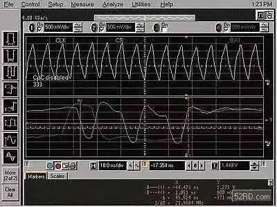
However, what are the common issues that can arise with signal integrity? Common problems include overshoot, glitches, slow edges, oscillations, glitches, timing violations, crosstalk, electromagnetic radiation, etc. These issues can all be classified as signal quality problems and signal integrity issues.

For example, here are some common issues (a brief list):
Overshoot
Anyone involved in hardware has likely encountered overshoot. It refers to the first peak or trough exceeding the predetermined voltage, appearing as a sharp pulse, which can often lead to circuit or component failure.
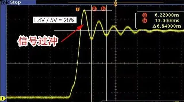
Overshoot can be categorized into two types: positive overshoot and negative overshoot, occurring during the rising and falling edges, respectively.
This overshoot typically occurs at the moment a power supply or circuit is turned on or off. An overshoot exceeding the normal voltage can potentially damage components and may also act as a source of interference, causing crosstalk with other circuits or components.
Moreover, if it is a negative overshoot, it will generate a negative voltage, which is a reverse voltage. For certain components in the circuit, this can create forward bias on the PN junction (parasitic diode), increasing the current in some circuits, which can lead to an open circuit if there is a fuse protection circuit.
Glitches
Similarly, glitches are also a very typical signal quality issue. They refer to the circuit output waveform exhibiting regular or irregular behavior for a very short time, which is not useful for design and may have adverse effects. They can easily cause misinterpretation of control signals or lead to phase issues or errors in clock signals.
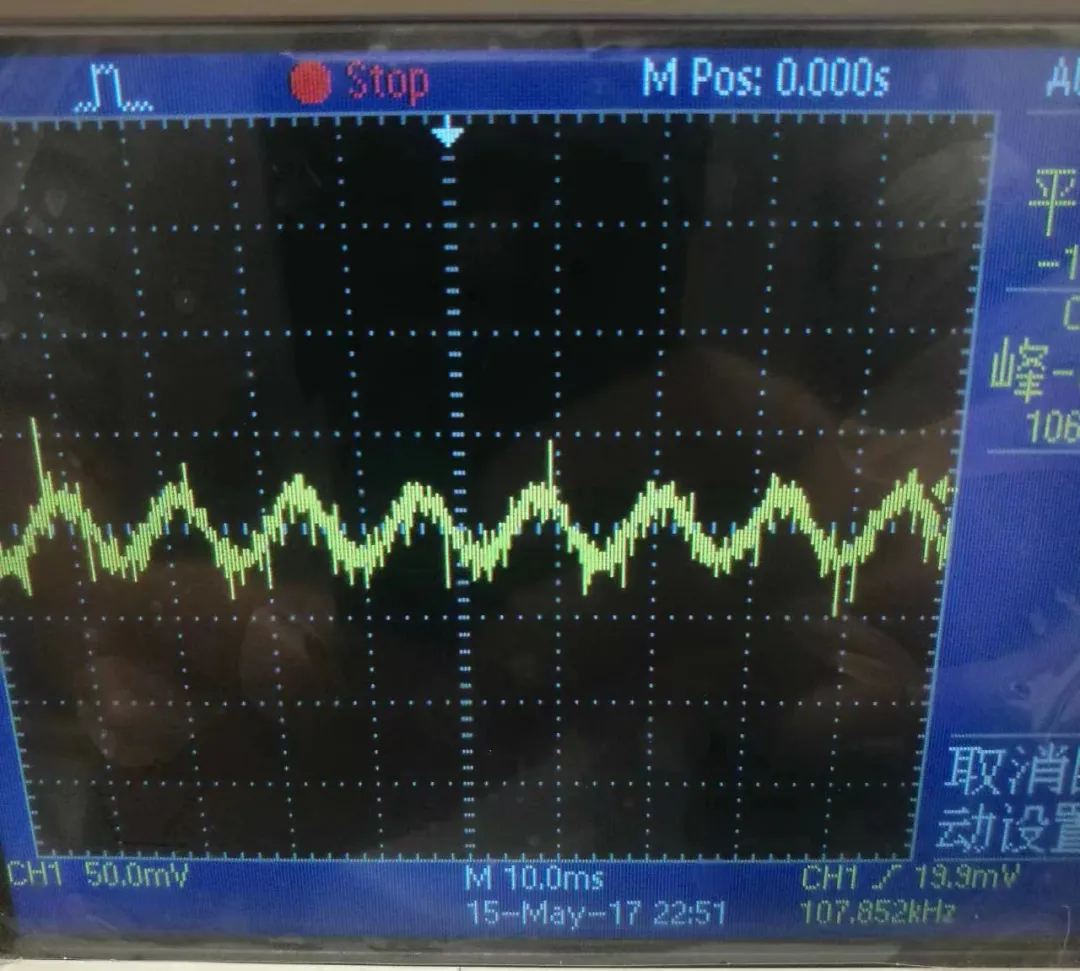
For instance, a high-level glitch may cause the signal to mistakenly interpret it as a high-level action, thereby sending corresponding commands and causing program chaos.
This typical glitch, although it rises and falls quickly, can lead to incorrect judgment if captured during data transmission. Additionally, for edge-triggered devices, if a glitch appears on the clock line, it may also be interpreted as a clock pulse, resulting in excess data being captured.
Glitches are very common in signal issues. Minor glitches can be ignored or avoided through software, but larger glitches need to be addressed; otherwise, they can lead to significant problems.
Glitches
Glitch issues can be very critical for certain signals, such as power signals. A glitch voltage may cause timing issues in the power-up sequence of a module, potentially leading to a system crash. Similarly, as mentioned earlier, if a glitch occurs in the clock signal, it can lead to unexpected level determinations, creating uncontrollable risks.
Setup Time / Hold Time Issues
Setup time and hold time are commonly referred to as Setup time and Hold time, which are timing concepts. For digital signals on circuit boards, they can be subdivided into clock signals, control signals, address signals, and digital signals. The relationship between these signals at a certain moment or within a certain time range defines their timing.
Setup time (Setup time) and hold time (Hold time) are two important indicators for determining timing relationships.
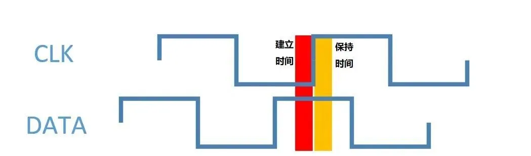
The official explanation is that setup time refers to the time during which data remains stable before the rising edge of the clock signal arrives at the trigger, while hold time refers to the time during which data remains stable after the rising edge of the clock signal arrives at the trigger.
Such tests are usually conducted on common signal protocols, such as I2C, SPI, SPMI, etc. If timing issues arise, the stability of signal communication will be affected.
When observing signal quality, ensure that the system is reliably grounded, and begin testing after the power is stable. The input power voltage should remain stable within a reasonable range (within 5% or 3% of the system voltage range).

Once the board is confirmed to be operating normally, you need to determine the selection of electronic instruments. The oscilloscope used must meet certain requirements, with a bandwidth at least greater than 3 to 5 times the signal bandwidth. If the bandwidth is insufficient, it may lead to slow rising edges or loss of signal details, affecting the actual judgment of signal quality.
Additionally, the sampling rate should be at least greater than 2 times the highest frequency of the signal.
As for the probes, if measuring high-speed signals, prioritize high-bandwidth, low-capacitance active probes (active probes should not be used to measure high voltage signals, such as 34V or higher, to avoid damaging the instrument) or differential probes. If the oscilloscope bandwidth is 5G, but the probe bandwidth is 1G, the probe will ultimately limit the signal testing, resulting in an overall effect of only 1G bandwidth.
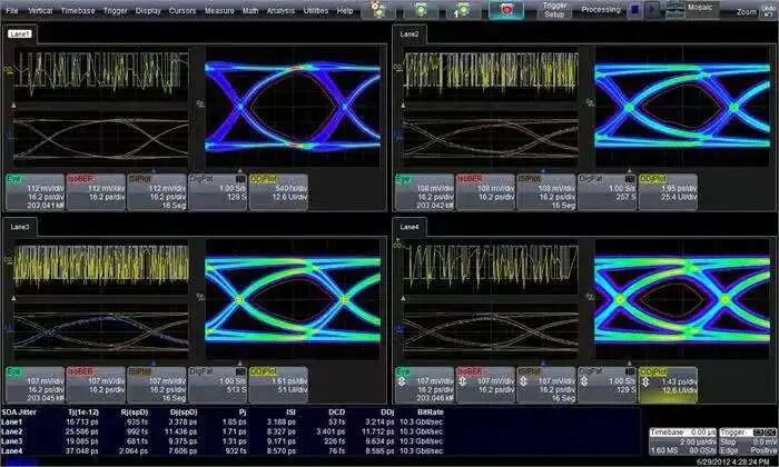
Before officially using the oscilloscope to observe signals, do not forget to calibrate the device.
For board signals, prioritize testing points close to the receiving end. For example, when observing the CLK signal of an SPI protocol, check the quality of the CLK signal from the device’s receiving end. If it is another protocol signal, such as bidirectional data signals, consider observing the signals at both ends.
(Other notes:
a. Try to ground the testing instruments with the single board to prevent measurement errors caused by floating ground lines.
b. When using differential probes to sample eye diagrams, at least 2000 overlays should be sampled; the more waveforms, the more accurate the test results.
c. When the probe is connected to the circuit, it becomes part of the circuit. At this point, the probe’s input capacitance will form a low-pass filter with the circuit’s output impedance. The cutoff frequency of this filter will affect the signal bandwidth we can observe, potentially causing slow rising edges or filtering out high-frequency details. Therefore, for high-speed signals, prioritize low-capacitance active probes.
)
If you want to learn more detailed content, you can click read the original text to jump!
Previous exciting content:
Must-read for beginners! The most common functions of diodes in circuits (Part 2)
Challenge your knowledge: Have you seen this bizarre chip packaging?
When can hardware work without overtime? A month of work reflections
From beginner to offer: A collection of common hardware engineer interview questions
Click here👇 to follow for more updates~
One-click three connections: “Share”, “Like”, and “View”
Updates 2-4 times a week~