Generally, based on the different reinforcing materials of the board, it can be divided into five categories: paper-based, glass fiber cloth-based, composite base (CEM series), laminated multilayer board base, and special material base (ceramic, metal core, etc.).If classified according to the different resin adhesives used in the board, common paper-based CCLs include: phenolic resin (XPc, XxxPC, FR-1, FR-2, etc.), epoxy resin (FE-3), polyester resin, and various types. Common glass fiber cloth-based CCLs include epoxy resin (FR-4, FR-5), which is currently the most widely used type of glass fiber cloth-based material.In addition, there are other special resins (with glass fiber cloth, polyamide fiber, non-woven fabric, etc. as reinforcing materials): bismaleimide modified triazine resin (BT), polyimide resin (PI), diphenyl ether resin (PPO), maleic anhydride-imide-styrene resin (MS), polycyanate resin, polyolefin resin, etc. According to the flame retardant performance classification of CCLs, they can be divided into flame-retardant type (UL94-V0, UL94-V1 grade) and non-flame-retardant type (UL94-HB grade).In the past one or two years, with increasing attention to environmental issues, a new type of bromine-free CCL has emerged in the flame-retardant CCL category, which can be called “green flame-retardant CCL”. With the rapid development of electronic product technology, there are higher performance requirements for CCLs. Therefore, based on the performance classification of CCLs, they can be further divided into general performance CCL, low dielectric constant CCL, high heat resistance CCL (generally above 150℃ for L), and low thermal expansion coefficient CCL (generally used on packaging substrates).Introduction to PCB circuit board materials: classified by brand quality level from low to high as follows: 94HB-94VO-22F-CEM-1-CEM-3-FR-4
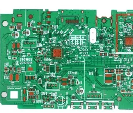
Detailed parameters and uses are as follows: 94HB: Ordinary paperboard, not fireproof (the lowest grade material, punchable, cannot be used for power boards) 94V0: Flame-retardant paperboard (punchable) 22F: Single-sided semi-glass fiber board (punchable) CEM-1: Single-sided glass fiber board (must be drilled by computer, cannot be punched) CEM-3: Double-sided semi-glass fiber board (the lowest grade material for double-sided boards besides double-sided paperboard, this material can be used for simple double-sided boards, 5-10 yuan/square meter cheaper than FR-4) FR-4: Double-sided glass fiber board The classification of flame retardant characteristics can be divided into four types: 94VO-V-1-V-2-94HB Prepreg: 1080=0.0712mm, 2116=0.1143mm, 7628=0.1778mm FR4 CEM-3 both represent board materials, fr4 is glass fiber board, cem3 is composite substrate Dielectric Constant of PCB Materials The study of the dielectric constant of PCB materials is important because the speed and signal integrity of transmission on the PCB are affected by the dielectric constant. Therefore, this constant is very important; hardware personnel often overlook this parameter because when manufacturers use different materials to make PCB boards, the dielectric constant is determined. For instance, the dielectric constant of Shengyi’s PCB board is 3.7, while that of Ultrasound’s PCB board is 4.2. According to the formula for the signal output speed on the PCB: where c is the speed of light, Er is the dielectric constant of the PCB board. Based on the above formula, some common conclusions can be drawn: 6mil/ps, 6inch/ns. According to Baidu Baike’s explanation, the dielectric constant: the medium produces induced charges when an external electric field is applied, which weakens the electric field; the ratio of the original external electric field (in vacuum) to the final electric field in the medium is the relative permittivity (relative permittivity or dielectric constant), also known as dielectric constant, which is frequency-dependent. The dielectric constant is the product of the relative dielectric constant and the absolute dielectric constant in vacuum. If a material with a high dielectric constant is placed in an electric field, the electric field strength will experience a significant decrease within the dielectric. The relative dielectric constant of an ideal conductor is infinite. Based on the dielectric constant of substances, the polarity of polymer materials can be judged. Generally, substances with a relative dielectric constant greater than 3.6 are polar substances; those with a relative dielectric constant between 2.8 and 3.6 are weakly polar substances; and those with a relative dielectric constant less than 2.8 are non-polar substances.
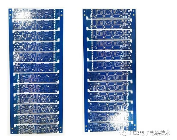
Dielectric Constant of FR4 Material
The dielectric constant (Dk, ε, Er) determines the speed at which electrical signals propagate in the medium. The speed of electrical signal propagation is inversely proportional to the square root of the dielectric constant. The lower the dielectric constant, the faster the signal transmission speed. Let’s make an analogy: it’s like running on the beach; if the water depth covers your ankles, the viscosity of the water is the dielectric constant. The more viscous the water, the higher the dielectric constant, and the slower you run. The dielectric constant is not very easy to measure or define; it is related not only to the properties of the medium itself but also to the testing methods, testing frequency, and the state of the material before and during testing. The dielectric constant can also change with temperature, and some special materials consider temperature factors during development. Humidity is also an important factor affecting the dielectric constant because the dielectric constant of water is 70, and even a small amount of moisture can cause significant changes. Dielectric loss of FR4 material: the energy loss caused inside the insulating material due to dielectric conduction and the lag effect of dielectric polarization when an electric field is applied. It is also called dielectric loss, abbreviated as dielectric loss. In an alternating electric field, the angle between the current phasor flowing through the dielectric and the voltage phasor (power factor angle Φ) is called the dielectric loss angle. The dielectric loss of FR4 material is generally around 0.02, and it increases with frequency. TG value of FR4 material: also known as glass transition temperature, generally is 130℃, 140℃, 150℃, 170℃. Common Thickness of FR4 Material Generally common thicknesses are: 0.3mm, 0.4mm, 0.5mm, 0.6mm, 0.8mm, 1.0mm, 1.2mm, 1.5mm, 1.6mm, 1.8mm, 2.0mm, and the thickness error of the board depends on the manufacturing capability of the board factory. Common copper thickness of FR4 copper-clad boards: 0.5 ounces, 1 ounce, 2 ounces; other copper thicknesses are also available, which need to be confirmed with the PCB manufacturer. Statement:This article’s copyright belongs to the original author and does not represent the views of the association.The articles pushed by the “Jiangxi Province Electronic Circuit Industry Association” are for sharing purposes only and do not represent the position of this account. If there are any copyright issues, please contact us for deletion.