Over 80,000 friends have followed the industrial control WeChat platform:Technical sharing,Learning exchange,Industrial control videos
-
Abstract: This article introduces an energy-saving retrofit system for inverters based on Siemens touch screens and PLC closed-loop control. The use of touch screens and PLCs in the closed-loop control energy-saving system allows operators to directly set target values (such as pressure and temperature) on the touch screen, compare them with actual values (measured by sensors) through PLC computations, and directly send computational instructions (analog signals) to the energy-saving inverter system to adjust the output frequency of the inverter. It also allows real-time monitoring of the actual values of the controlled system and multiple parameters within the inverter, achieving functions such as alarms and record-keeping.
-
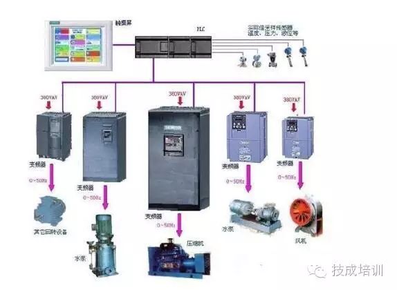
The application of Siemens touch screens combined with Siemens PLCs in the closed-loop control energy-saving system for inverters reflects a trend towards automated control. The use of touch screens and PLCs in the closed-loop control energy-saving system allows operators to directly set target values (such as pressure and temperature) on the touch screen, compare them with actual values (measured by sensors) through PLC computations, and directly send computational instructions (analog signals) to the energy-saving inverter system to adjust the output frequency of the inverter. It also allows real-time monitoring of the actual values of the controlled system and multiple parameters within the inverter, achieving functions such as alarms and record-keeping. The closed-loop regulation energy-saving system with PLC and touch screen is shown in the figure below.
-
-
-
Figure 1: Schematic of the inverter energy-saving system controlled by the touch screen combined with PLC
-
2. Uses of the Closed-Loop Control Energy-Saving System The closed-loop control energy-saving system has a wide range of applications, with different driving and control methods for various scenarios. Specific applications should be selected based on actual conditions. Some examples include: Central air conditioning energy-saving: chiller pumps, cooling pumps, main units, cooling tower fans, fan coil units, etc. Constant pressure water supply: first and second stage pumps in water plants, booster pumps in water supply networks, building water supply pumps, etc. Boilers: induced draft fans, blowers, feed pumps, etc., with control and adjustment signals provided by the boiler automatic control system, DCS, or multi-pulse control systems. Steam turbines: circulation pumps, condensing pumps, etc., with control and adjustment signals provided by the steam turbine automatic control system and DCS. Pure water treatment systems: softening pumps, booster pumps, etc. Clean rooms: booster fans, FFU group control, etc.
-
3. Components and Functions of the Entire Closed-Loop Control Energy-Saving System(1) PLC selected is Siemens S7-200 series: consisting of CPU224XP, DIDO modules, and AIAO modules. The PLC serves as the control unit and the core of the entire system. Its main functions include: ① Collecting various data from the system and converting digital and analog signals. ② Performing logical control and PID adjustment calculations for the entire system. ③ Providing collected and processed data to the touch screen and executing various commands issued by the touch screen. ④ Converting PID calculation results into analog signals to control the output frequency of the inverter. ⑤ Reading and writing internal parameters of the inverter via communication cables and USS4 protocol. (2) The touch screen used is Siemens MP370: Its main functions are as follows: ① Real-time display of the operational status of devices and systems. ② Sending commands and data to the PLC through touch input, with the PLC controlling the system or devices. ③ Creating multiple monitoring screens, replacing traditional electrical operation panels and display recording instruments, and offering more powerful functionality. (3) Inverter: Siemens 440 series is used, which can have some internal parameters set via the touch screen through the PLC using USS4 protocol, adjusting the speed of pumps or fans based on the data (analog value) sent from the PLC and feeding back internal operating parameters to the PLC. (4) Sensors for pressure, temperature, etc.: Convert the actual parameter values of the controlled system (water or air system) into electrical signals sent to the PLC. (5) Electrical components: Provide power to the PLC, touch screen, inverter, and sensors to complete various operations and drives.
-
4. Touch Screen Interface Design The touch screen interface is designed using specialized software such as ProTool, then debugged through a programming computer before being downloaded to the touch screen once qualified. The total number of screens should be within the limits of its storage capacity, and screens should allow mutual and forced switching as much as possible. (1) Design of the main screen: Generally, a welcome screen or the main system screen of the controlled system can serve as the main screen, which can lead to various sub-screens. Each sub-screen should be able to return to the main screen in one step. If the main system screen of the controlled system is used as the main screen, it should display some key parameters of the controlled system for a general understanding of the entire controlled system. (2) Design of control screens: These screens are primarily used to control the start and stop of the controlled devices and display internal parameters of the inverter, with the setting of inverter parameters also possible within them. This type of screen occupies the majority of the touch screen screens, with the specific number of screens determined by the actual controlled devices. (3) Design of parameter setting screens: This screen is primarily for setting the internal parameters of the inverter, and it should also display the status of parameter setting completion, with encryption considerations during actual production. (4) Design of real-time trend screens: This screen mainly displays the controlled values and key working parameters of the inverter (such as output frequency) in a curve recording format. (5) Design of information recording screens: This screen mainly records possible equipment damage, overload, out-of-range values, and emergency stops, etc. Additionally, this screen can record the start and stop operations of each device as proof. (6) Design of energy-saving screens: This screen mainly records and displays the accumulated electricity consumption of the inverter and real-time energy-saving status, in order to demonstrate the benefits of energy savings to users, and can also be used for comparison with other energy-saving measurements.
-
5. PLC Program Design The PLC program is designed using S7-200 specialized programming software, then downloaded to the PLC for online debugging via a programming computer, and can be used once qualified. Before programming the PLC, the addresses of each functional program segment should be planned to avoid reusing the same address, which could cause misoperation. (1) Design of logical functions: This part of the program mainly completes the start and stop, interlocking, and automatic switching functions of various inverters and water pumps (or fans), and the software logic function testing can generally be completed in offline mode. (2) Design of PID functions: The PID adjustment program can be completed using the PID wizard in S7-200, with specific configurations determined based on the actual controlled devices and sampling devices. (3) Design of sampling programs: When using standard configurations for sampling elements, attention should be paid to whether the specific data after AD conversion matches with PID and display programs, and actual production should also consider multi-channel and related sampling situations. (4) Design of communication programs between PLC and inverter: Communication between Siemens S7-200 PLC and Siemens 430 series inverters generally uses USS4 protocol programs to monitor the real-time operational status of the inverter. (5) Design of other auxiliary programs: During actual programming of the PLC, consideration should be given to patching some programs to minimize program vulnerabilities, and continuous refinement and improvement should be undertaken.
-
Conclusion
In the closed-loop control energy-saving system, using a touch screen allows users to intuitively monitor the entire central air conditioning energy-saving system and its associated devices and systems, improving the automation level and hardware quality of the entire controlled system and enterprise.
Source: Industrial Control Network
Don’t forget to share this great content with your friends!


Long press to recognize the QR code
Follow Jicheng Training
ClickRead the original textto seeJicheng Training Network, learn more PLC knowledge!
↓↓