 1. First, set to “Modbus RTU protocol” through [Pr.PC71].Set the “Control Mode Selection” of [Pr.PA01] to program control mode.2. Set the homing reset mode at address 6098H (for example, the commonly used return method with DOG search).3. Save the manufacturer-defined parameters in EEPROM at address 1010H, then power off and restart.4. In Point Table Mode, at startup, set the homing reset speed and creep speed at address 6099H.Set the acceleration time constant and deceleration time constant at address 2801H.In Program Drive Mode, at startup, set the homing reset speed and creep speed at address 6099H.Set the acceleration time constant at address 211EH and the deceleration time constant at address 211FH.Save EEPROM again.5. Set the Homing Mode at address 6060H.6. Confirm mode switching through address 6061H.7. Set 0FH → Operation enable at address 6040H.8. In Point Table Mode, set 1FH at address 6040H to start the homing reset.In Program Drive Mode, set 1FH at address 6040H, or specify Program Drive Mode at address 6060H and include the ZRT command to start the homing reset through the execution program.9. Confirm that bit 12 (Homing attained) at address 6041H changes to “1”.10. Homing reset is complete.Below are the specific usage details for each address.Control Instruction Register Address: 6040H, as previously introduced, use function code “10H” to change bit 4 to “1” to start the homing reset.Homing Reset Mode Register Address: 6098H
| Address | Name | Data Type | Read/Write |
| 6098H | Homing Reset Mode | 1 byte | Read/Write |
Read and write operations can be performed, and function code “03H” can be used to confirm the current homing reset mode.Use function code “10H” to set the homing reset mode. To ensure that the written homing reset mode remains effective after power is restored, the EEPROM write command (1010H) must be executed. After executing the EEPROM write command, the set values of [Pr.PT04] and [Pr.PT45] will change.Details on selecting the homing reset mode are as follows: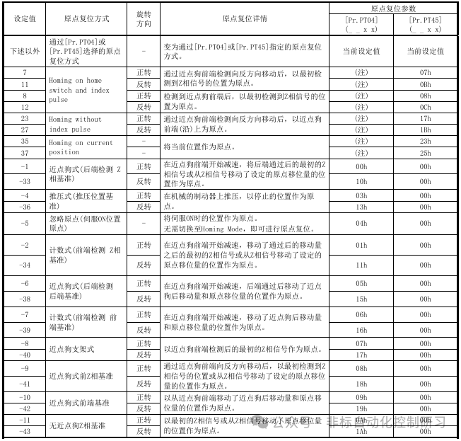 Homing Reset Speed Register Address: 6099H
 Read and write operations can be performed, and function code “03H” can be used to confirm the current homing reset speed. At this time, respond with “02h” for the Number of entries.Use function code “10H” (to write multiple holding registers) to set the homing reset speed. At this time, write “02h” in the Number of entries.After completing the above settings, the current control status can be confirmed through register address: 6041H.
| Address | Name | Data Type | Read/Write |
| 6041H | Control Status | 2 bytes | Read |
Only read permission is available, and function code “03H” can be used to confirm the current control status.
| Bit | Content |
| 0-9 | Refer to previous text |
| 10 | Target reached |
| 11 | Refer to previous text |
| 12 | Homing attained |
| 13 | Homing error |
| 14-15 | Refer to previous text |
(a) Bit 10 (Target reached) of Control Status (6041H) changes to “1” when the target position is reached. When bit 8 (Halt) of the control instruction is set to “1”, it changes to “1” after deceleration and stop are completed. If a command is input again, it changes to “0”.(b) Bit 12 (Homing attained) of Control Status (6041H) changes to “0” when the homing reset starts and to “1” when the homing reset is complete. When using an absolute position detection system, it changes to “1” after power is turned on.(c) Bit 13 (Homing error) of Control Status (6041H) changes to “1” if an alarm or warning occurs during the homing reset [AL 90.2], [AL 90.3], [AL 90.5], [AL 96.1], [AL 96.2], [AL 96.3].The settings are essentially consistent with the parameters that need to be set for terminal wiring control, and the signal points used are the same; one uses hardware wiring, while the other uses communication.