Creating Ethernet Communication Between Siemens Touch Screen and S7-200 SMART CPU
Configure Communication Connection
Users can create Ethernet communication between the Siemens touch screen and the S7-200 SMART CPU through the following steps, taking the Smart 1000 IE device as an example.
In the main workspace of WinCC flexible, add a connection to the CPU similar to the RS485 interface of the Siemens touch screen mentioned above, which will not be repeated here. The following mainly introduces connection parameter settings and project downloads.
To set the connection parameters, first select the Smart 1000 IE interface as “Ethernet”, which is the Ethernet interface of the touch screen. After selecting this interface, the parameter setting window for this interface will automatically display below. Set the touch screen’s IP address to 192.168.2.5, which must be the same as the IP address of the Smart 1000 IE device. Set the CPU’s IP address in the “PLC Device” window; here the CPU’s IP address is set to 192.168.2.1, as shown in Figure 1.
Note: The IP address set for Smart 1000 IE must be different from the CPU’s IP address; the two cannot be the same.
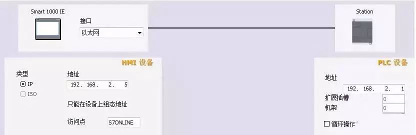
Figure 1. Setting Communication Parameters
After completing the connection parameter settings, the IP address of the Smart 1000 IE device also needs to be set. In the touch screen’s “Transfer Settings” interface, click the “Advanced” button in the lower left corner, and in the “Ethernet Settings” dialog box, enter the Smart 1000 IE’s IP address 192.168.2.5 and subnet mask. After entering, click the “OK” button in the upper right corner of the dialog box to save the settings, as shown in Figure 2.
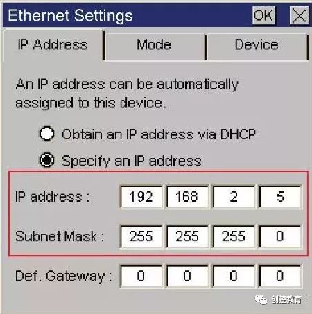
Figure 2. IP Address of Smart 1000 IE
Download Project File
To download the configured project to the Smart 1000 IE device, ensure that the HMI device’s communication port is activated, which can be set through the HMI device’s “Control Panel” > “Transfer”. When selecting the Ethernet method to download the project, check the “Enable Channel” option next to “Ethernet”, as shown in Figure 3.
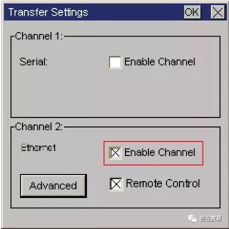
Figure 3. Enabling Communication Port
In the menu bar of WinCC flexible software, select “Project” > “Transfer” > “Transfer”, and click “Transfer” to open the “Select Device for Transfer” window, as shown in Figure 4. In the “Select Device for Transfer” window, set the transfer mode to “Ethernet” and enter the HMI device’s IP address in the “Computer Name or IP Address” field, which should be set to 192.168.2.5 as mentioned above.
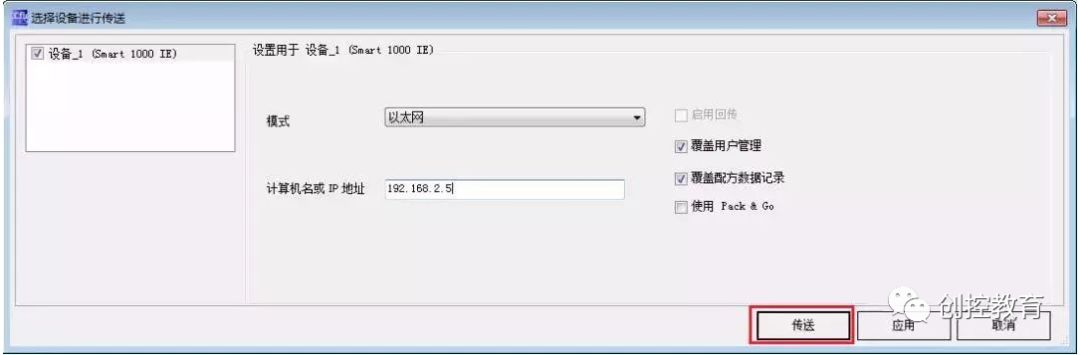
Figure 4. Transfer Settings
After completing the IP address settings, click the “Transfer” button in Figure 4. When the transfer status shows “Transfer Complete”, the project has been successfully transferred to the HMI device via Ethernet mode.
(Content sourced from the internet, copyright belongs to the original author)
Disclaimer: If there are copyright issues, please contact for deletion! No individual or organization bears legal responsibility.