Stepper motors are commonly used for positioning control, and their rotation angle (which can also be considered as distance) is controlled by the number of pulses output from the PLC. The frequency of the pulses controls the speed of the stepper motor. For applications where control precision is not critical, this method is simple, economical, and easy to control; however, for applications requiring high precision, a servo control system must be used.
The stepper system consists of a stepper driver and a stepper motor. The stepper motor is driven by the stepper driver, which acts as the power supply and is controlled by external pulse and direction signals (for example, pulses output from a Siemens PLC), thereby controlling the rotation angle and speed of the stepper motor.

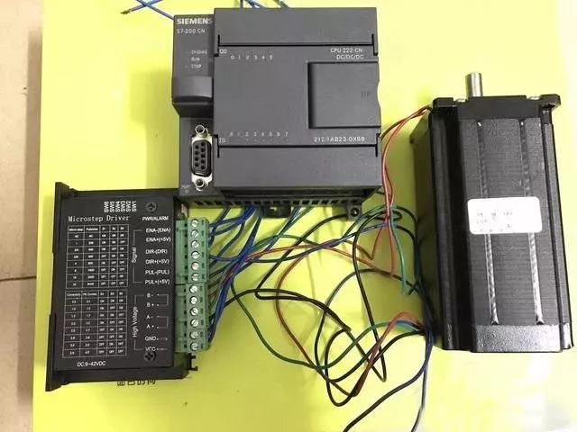
Stepper driver + stepper motor + Siemens PLC (CPU 222 CN)
Related Definitions
1. Driver: The medium used for PLC control of the stepper motor, responsible for amplifying the pulse signals from the PLC and delivering them to the stepper motor, allowing the motor to operate according to the parameters set by the PLC and driver.
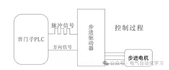
Control Process
2. Step Angle: The angle of rotation for each pulse sent to the stepper motor, commonly set at 1.8°, which is generally fixed.
Example: Without setting microstepping, how many pulses does the PLC need to send for a stepper motor with a step angle of 1.8° to complete one full rotation (360°)?
Answer: 360°/X=1.8°/1, thus X=200 pulses.
3. Microstepping: In practical applications, a large step angle results in significant rotation per step, which can cause vibrations and increase control errors. Therefore, microstepping is introduced. This means dividing the step angle into smaller increments using the DIP switches on the driver, allowing for smoother motor operation.
Example: With a step angle of 1.8° and set to 10 microsteps, each pulse from the PLC will only rotate the motor by 0.18°. How many pulses does the PLC need to send for the stepper motor to complete one full rotation (360°)?
Answer: 360°/X=0.18°/1, thus X=2000 pulses.
Summary: The larger the step angle, the fewer the number of pulses required; the smaller the step angle, the more pulses are needed.
Introduction to Stepper System Hardware (Using Pfiedler Stepper Motor as an Example)
1. Stepper Driver
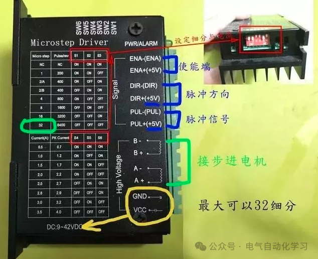
Pfiedler Driver Description
There are generally two methods for controlling the direction of the stepper motor:
A) Pulse + Direction: When a pulse is generated at PUL, the motor will rotate, and the direction is determined by DIR.
B) Forward Pulse + Reverse Pulse: When a pulse is generated at PUL, it rotates forward; when a pulse is generated at DIR, it rotates in reverse. However, PUL and DIR cannot have pulses generated simultaneously.
2. Stepper Motor
Reversing the A and B phase windings will cause the motor to rotate in the opposite direction.
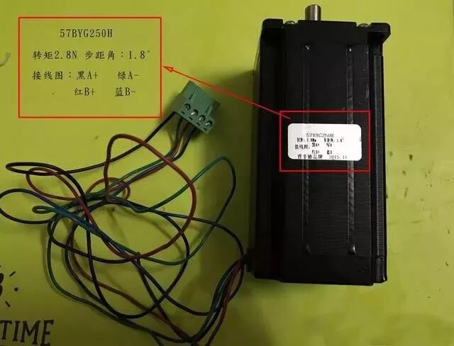
Stepper Motor Parameters
Wiring Diagram with PLC
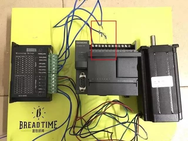
The signal voltage for this stepper motor is 5V, while the Siemens PLC operates at 24V. Therefore, to connect to the driver, a 1.2K, 1/4W resistor must be connected in series, as shown in the red part of the diagram.
Siemens PLC (CPU222) can output high-speed pulses in two ways:
1. PTO (50% duty cycle)
2. PWM (variable duty cycle)
Using these two types of high-speed pulse output commands, the stepper driver can be controlled, which in turn controls the stepper motor, allowing for the movement and speed control of specific devices.