1. Module Overview
| Project Name | Detailed Parameters | Remarks |
| Hardware Power Supply | DC 10V-24V @ No Load 0.1A | Protection Current 1.5A |
| Output DQ | 8-channel solid-state relay output, response time less than 5ms | Protection Current 0.7A |
| Input DI | 8-channel opto-isolated input, compatible with NPN sensors | |
| Input AI | 4-channel 24-bit ADC high-precision analog signal acquisition, range 3300mV | ADS1220 chip |
| High-speed Pulse | 8-channel PWM signal output, applicable to motor drivers | |
| Communication Expansion | 01. Optional CAN communication, RS485, serial communication02. Reserved DB9 for SPI, I2C, UART bus expansion |
This PLC controller is an industrial-grade programmable logic controller designed based on the STM32F407 microprocessor. It features various interface resources, including digital input/output, PWM waveform generation, and high-precision analog signal acquisition, and supports optional configuration of CAN or RS-485 communication protocols. It is suitable for applications requiring precise control and monitoring.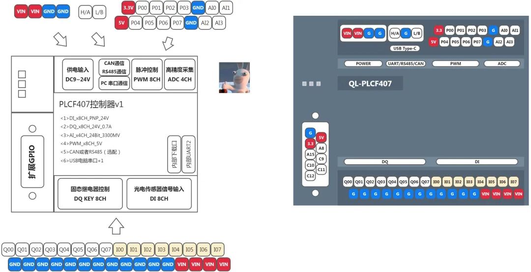
DQ Output
- Quantity: 8 Type: Solid State Relay
- Function: Can directly drive loads such as bulbs, solenoids, etc.
- Notes: Ensure that the load does not exceed the maximum capacity of the relay during use.
DI Input
- Quantity: 8 Type: PNP Opto-isolated
- Function: Used to receive the status feedback of external switches or other devices.
- Notes: Ensure that the input signal meets the PNP type requirements.
PWM Output
- Quantity: 8 Voltage Level: 5V TTL
- Function: Generates square wave signals with adjustable duty cycles, suitable for servo motor speed control.
- Notes: Before connecting, please confirm that the target device can accept TTL level signals.
ADC Analog Signal Acquisition
- Channel Count: 4 Resolution: 24-bit
- Function: High-precision sampling of analog quantities such as temperature sensors and pressure gauges.
- Notes: To ensure measurement accuracy, please set the sampling frequency correctly and take anti-interference measures.
Communication Interface
- Supported: CAN or RS-485 (one of the two)
- Function: Enables data exchange with other devices, suitable for building remote monitoring systems.
- Notes: Choose the appropriate communication method based on actual needs and follow standard wiring specifications.
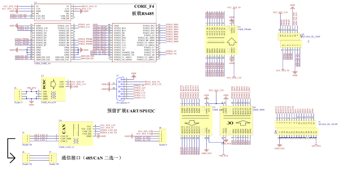
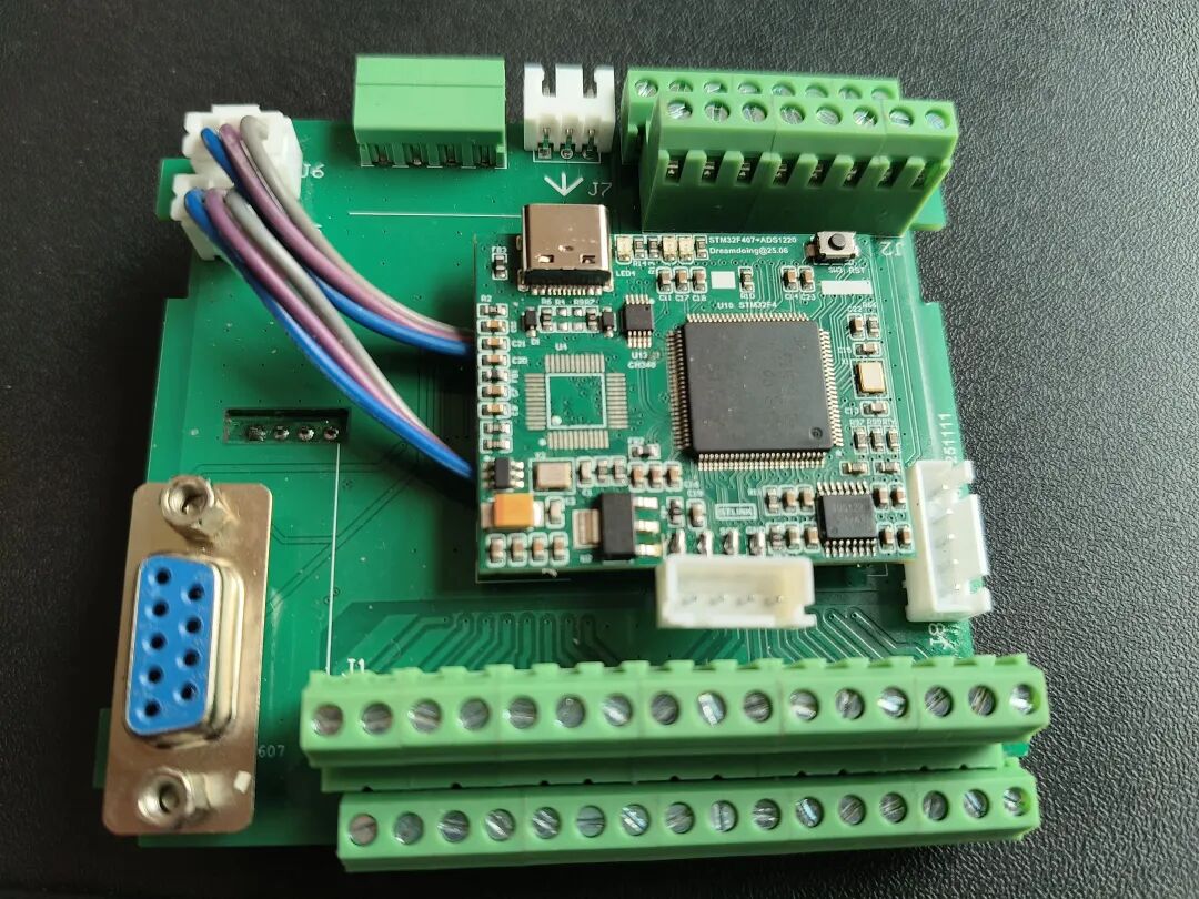
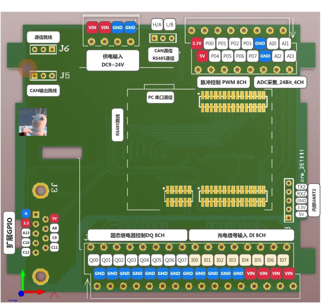
2. System Circuit Diagram
 [1] The carrier board integrates the STM32F407 module, solid-state relay module, switch signal input, PWM output, and ADC acquisition;
[2] The carrier board outputs 5V and 3.3V power supply to meet the power supply requirements of various modules;
[3] Use of jumpers, if only using CAN or RS485, connect the 3P2.54 wire to [J6], if both CAN and RS485 are used, then J5 should be connected separately;
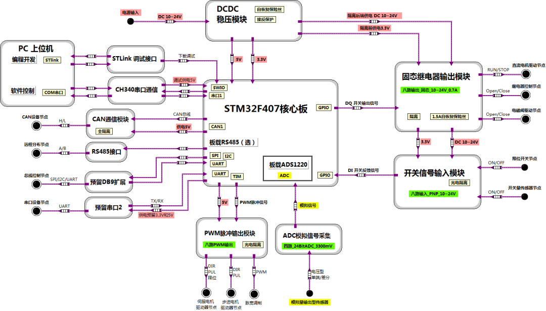
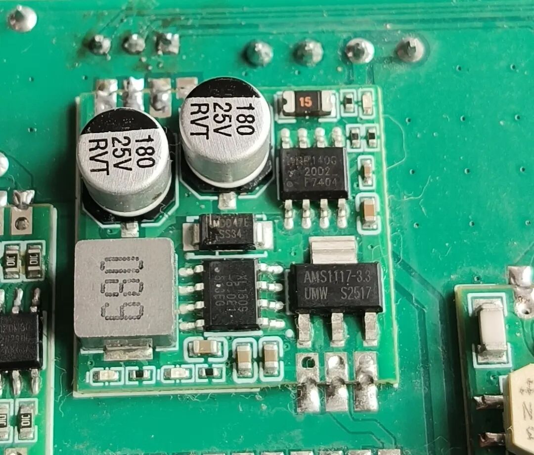
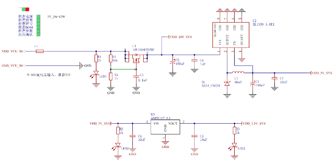
[01] DCDC voltage regulator module, responsible for stepping down to 5.0V and 3.3V to power the internal circuits of the system;
[02] STM32F407 core board, the solution is CH340 + main control chip + onboard ADC chip + RS485 (optional)
[03] Solid-state relay output module, responsible for outputting driving voltage, compatible with voltages from 10V to 24V;
[04] Switch signal input module, responsible for receiving signals from switch-type sensors;
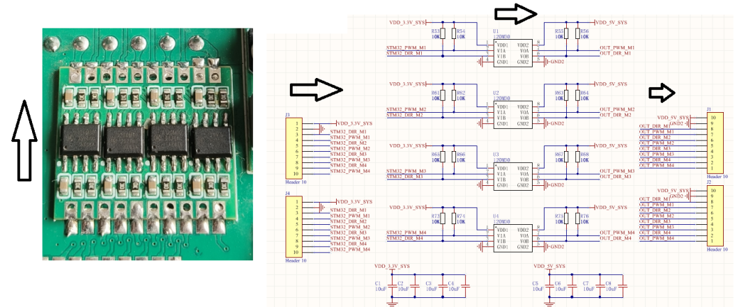
[05] PWM pulse output module, responsible for outputting pulse signals for the drive’s pulse width modulation;
[06] High-precision ADC acquisition module, parameters are four-channel_24-bit_3300mV;
[07] DB9 interface, used for expanding I2C/SPI/UART communication for modules;
[08] Internal jumpers, coordination between CAN and RS485,
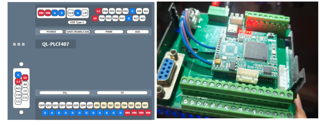
3. STM32F407 Core Board
[01] Four-layer board design for better signal shielding
[02] Compatible with PLC housing, standardized design
[03] Modular design for easier maintenance or troubleshooting
[04] High and low wiring terminals, multiple ground and VIN outputs, reducing expansion and facilitating wiring
4. Solid State Relay Output Module
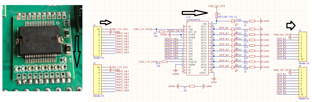
[01] Integrated design using solid-state relay chips, enhanced overcurrent protection, reduced footprint
[02] Module can directly output driving power, single-channel current protection is 0.7A, total fuse is 1.5A
[03] Module can be applied in solid-state relay circuits of 10V-24V, removing the GND 0R resistor can achieve isolation
[04] Module half-hole design, can be directly soldered or mounted on the circuit board;
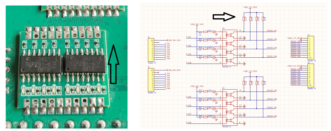
5. Digital Switch Sensor Signal Input Module
6. PWM Pulse Signal Output Module
7. DCDC0533 Step-down Voltage Regulator Module
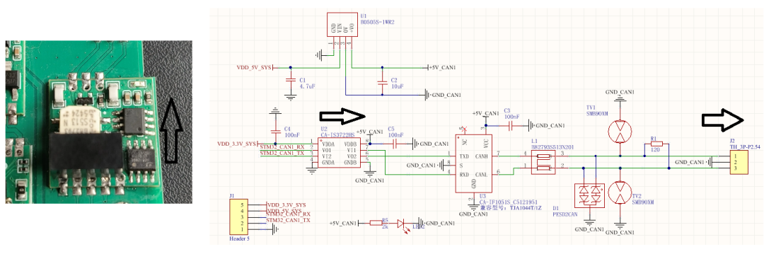
8. Fully Isolated CAN Communication Module
9. About Us
Device Name: PLCF407 Industrial Controller
Device Parameter 1: 24-bit, four-channel, 1ksps,
Device Parameter 2: 8-channel solid-state output, 8-channel opto-isolated input, 8-channel PWM output, 1-channel CAN/485
Device Manufacturer: Qianli Youxuan Teaching Base
Sales Channel: Taobao Shop [Dayu Xiaoshui’s Electronics Store](Click the original link at the end of the article)
10. Disclaimer01. All software and hardware materials in this tutorial are original, and copyright belongs to Qianli Youxuan Teaching Base;02. This tutorial is for technical sharing,applied in the teaching field, and related code technical content is for reference only;03. Internal materials, for reference learning only, commercial use is prohibited;04. Note: Use the mobile WeChat client to browse relatedhigh-definitionimages;