Friends who do automation debugging or maintenance have likely encountered this scenario: the PLC suddenly lights up a red alarm, the screen flashes unfamiliar codes, and in a panic, you frantically flip through the manual, only to find yourself more confused. In fact, most mainstream PLCs come with a built-in “self-diagnosis” function. The key to fixing a PLC is not to guess the problem but to fully utilize this diagnostic feature to accurately locate the fault point.
Today, I have compiled 8 common types of PLC errors that I frequently encounter during maintenance, along with corresponding troubleshooting tips—no complex terminology, just practical methods summarized from real-world experience, so even beginners can follow along step by step!

 🔴 1. Abnormal CPU Alarm
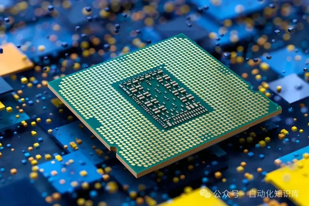
The CPU is the “brain” of the PLC. When it alarms, we should first focus on “all devices connected to the CPU unit and internal bus”.
My usual troubleshooting method is as follows: for example, if a PLC in the workshop reports a CPU error, I will first replace it with a spare CPU module—if the alarm disappears after the replacement, then the original CPU unit is faulty; if the alarm persists, I will sequentially replace the adjacent expansion modules and communication modules, testing one at a time to gradually narrow down the range. There’s no need to rush to disassemble the entire unit; by replacing units one by one, you can quickly find the “problematic unit” and then repair or replace it.
 🟡 2. Abnormal Memory Alarm
The memory is where the program is stored. When it alarms, don’t rush to replace parts; first try “reprogramming”.
I once encountered a situation where the PLC reported a memory error. I re-downloaded the program, and it surprisingly worked! Later, it was found that a strong noise from the variable frequency drive in the workshop had “disrupted” the program. However, if the alarm does not disappear after reprogramming, it is likely that the memory itself is faulty—at this point, you will need to replace the memory module, and remember to back up the original program before replacing it to avoid losing important parameters.
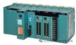
 🟢 3. Abnormal Input/Output (I/O) Unit and Expansion Unit
The most common reason for this alarm is actually “loose wiring”, which is much more likely than hardware failure.
The first step is to check the “physical connections”: gently shake the connectors of the I/O unit and expansion unit to see if they are loose; then follow the cables to check for any frayed spots or places that may have been chewed by mice (which is quite common in workshops!). Once you determine which unit is problematic, for example, if you find that a certain input unit’s connector is loose, reinsert it tightly. If that doesn’t work, try replacing it with a spare unit—this usually resolves the issue without initially suspecting that the module is faulty.
 🔵 4. PLC Not Executing Program at All
If the PLC is not running the program at all, don’t press buttons randomly. Check in the order of “Input → Program Execution → Output”, and you won’t go wrong.
(1) First check “Input”: Look at the LED lights + Multimeter
First, check the input LED lights on the PLC panel—if you press the “Start Button”, the corresponding input light (e.g., I0.0) should light up.
- If the light does not turn on: suspect an external issue. I will use a multimeter to measure the voltage at the PLC input terminal. If the voltage is incorrect (e.g., not 24V), then the button is faulty or the wire is broken; if the voltage is normal but the light does not turn on, then the input unit is faulty.
- If the light is on, but the corresponding input point does not show on the programmer’s monitor: then the input unit, CPU unit, or expansion unit may not be connected properly. Check the module connections one by one.
(2) Next check “Program”: Use the monitor to view the ladder diagram
Open the programmer’s monitor and compare it step by step with the ladder diagram—for example, if a certain contact should be closed but the monitor shows it is open, then either the program is written incorrectly (I have made this mistake before: using the same internal relay twice caused a conflict), or there is an issue with the PLC’s computation part. By carefully comparing, it is easy to find the error.
(3) Finally check “Output”: Again, look at the LED lights + External Load
- If the program’s computation result is correct (e.g., the monitor shows output point Q0.0 is on), but the LED light is off: then there is a problem with the CPU unit or I/O interface unit.
- If the LED light is on, but the external device (e.g., solenoid valve) does not operate: first measure the voltage at the output terminal. If there is no voltage, the output unit is faulty; if there is voltage, then the solenoid valve coil is burned out or the wire is broken.
Just a reminder: the LED positions vary among different brands of PLCs; some are on the I/O interface, while others are on the I/O unit. Before checking, make sure to look at your PLC model to avoid looking at the wrong light!
🟣 5. Some Programs Not Executing
The troubleshooting method for this situation is similar to that of “not executing the program at all”, but there is an easily overlooked detail:Input Signal Duration Too Short.
For example, components like counters and step controllers may not register if the input signal only jumps for 0.1 seconds and then disappears; the PLC may not respond in time. I encountered this when debugging a production line where the counter was not counting. Later, I discovered that the sensor’s trigger signal lasted only 0.1 seconds, while the PLC input unit’s maximum response time was 0.2 seconds, which was simply too short to recognize.
We can calculate whether the time is sufficient: the input time must be greater than “maximum response time of the input unit + scan time × 2”. If it is not enough, either add a delay in the program or adjust the sensor’s trigger duration, and the problem will be resolved.
 🟤 6. Power Interruption Causes Program Loss
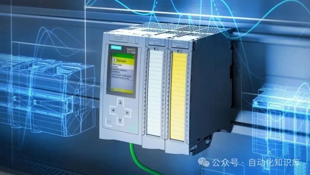
This issue is really frustrating, especially when the program is not backed up! We will check according to these four steps:
(1) First check the battery
Many PLCs rely on batteries to save programs. I will first check the battery indicator light—if the red light is on, I will remove the battery to see if there is any leakage or bulging. If so, I will replace it with a new battery (remember to keep the PLC powered on while replacing, otherwise the program may be lost).
(2) Try repeatedly turning the PLC power on and off
The PLC has an “initial reset circuit” and a “power-off program retention circuit”. If these parts have poor contact, the program will not be retained. I once encountered a situation where after turning the power on and off three times, the program was retained once. Later, it was found that the reset circuit’s wire was loose, and resoldering it fixed the issue.
(3) If the alarm persists after replacing the battery, check for leakage current or memory issues
If the new battery does not resolve the battery error, then either the memory is faulty or the leakage current in the external circuit is too high. I will use a multimeter to measure the current in the external circuit; if it is significantly higher than the normal range, I need to check for grounding or short circuits in the wiring.
(4) Is the power interruption synchronized with the machine? Check for noise
For example, if the PLC loses power when the machine starts and works fine when the machine stops, this is likely due to strong noise interference from the machine. I once added a filter next to a large motor in the workshop, and the noise during the motor startup was filtered out, so the PLC no longer lost power and lost the program.
⚫ 7. PROM Not Working
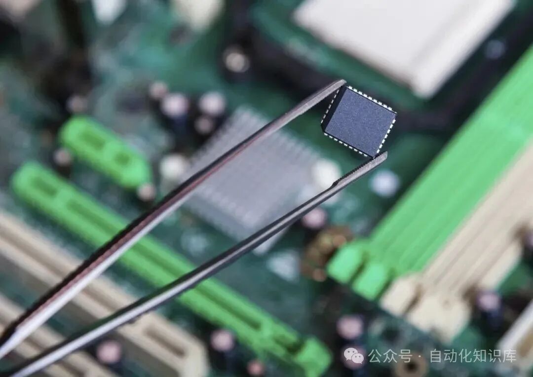
PROM is the chip that stores the program. If it is not working, don’t rush to replace it; first check the “contacts”.
I will first remove the PROM chip to check if the pins are bent, broken, or covered in dust—sometimes it’s just a loose connection causing poor contact. Clean the pins, reinsert them tightly, and try again. If it still doesn’t work, then replace it with a new PROM chip (remember to burn the original program into it before installing an empty chip).
 ⚪ 8. Actions Stop After Power Restart or Reset
For example, if the PLC restarts and the previously running motor or cylinder suddenly stops, don’t panic. First, check two points:
- Program “Hold Logic”: Did you use a non-latching instruction? For example, if the signal disappears after the button is released, it will naturally not operate after a restart. In this case, just add a latching instruction in the program.
- Power Retention Function: Many PLCs require manual activation of certain registers’ “power retention”. If it is not activated, data will reset after a restart, causing actions to stop. You can find this in the PLC’s system settings and check the registers that need to be retained.
- Reset Circuit: If the PLC does not initialize properly after a restart, actions will also stop. At this point, check if the reset signal is normal and if there are any abnormal reset triggers.
These are the 8 common PLC errors and troubleshooting methods I have compiled, all based on little experiences gathered during maintenance—actually, PLC alarms are not scary. As long as you follow the thought process of “diagnostic function → physical connection → program → external load”, most problems can be solved.
If you have encountered other PLC faults or have more practical troubleshooting tips, feel free to share in the comments section—we can exchange ideas and avoid taking unnecessary detours.
Previous Recommendations
Want to learn Siemens PLC programming well? Don’t miss this instruction usage!
Save! 150 basic electrical questions for electricians to practice?
DeepSeek is on fire; will PLC engineers be unemployed? The truth may not be what you think.
Essential for electrical personnel! A comprehensive guide to PLC control cabinet design, from wiring to principles, easy to understand.
Don’t panic if the frequency converter is broken; remember these tips to solve most problems!
Attention electrical and electronics personnel! 50 super practical classic circuit diagrams, essential for design, be sure to save them!
Illustrated examples of complete electrical cabinet installations, worth saving!
Three minutes to solve complex switch cabinets, even beginners can understand!
Little tips used by senior engineers: HMI multiplexing variables, easy for beginners to grasp!
Embedded vs. PLC programming: which one is more suitable for you? This article explains it clearly.
 Share
Share Save
Save View
View LikeFollowSo you can find me next time