Click 【Industrial Automation Insights】 to follow us!
Source: Industrial Control Automation Zhuge Liang
Why Does Your PLC Program Keep Throwing Errors? 90% of the Problems Are Due to These Four Units!
Why does the program throw a ‘data type mismatch’ error when it runs, even though it was written according to the tutorial? Why can the Mitsubishi PLC store 16 bits in the D0 register, while Siemens can store 32 bits? When using Modbus communication, should a double word read 2 or 4 registers?
As the brain of industrial automation, the data storage units of PLCs (bit, byte, word, double word) are the foundation of programming. However, 80% of beginners have stumbled over these invisible units.
In this article, we will use3 metaphors + 4 cases + 1 universal table to help you thoroughly understand their relationships, so you won’t fall into pitfalls while programming!
1. Understanding the Four Units Through Everyday Analogies
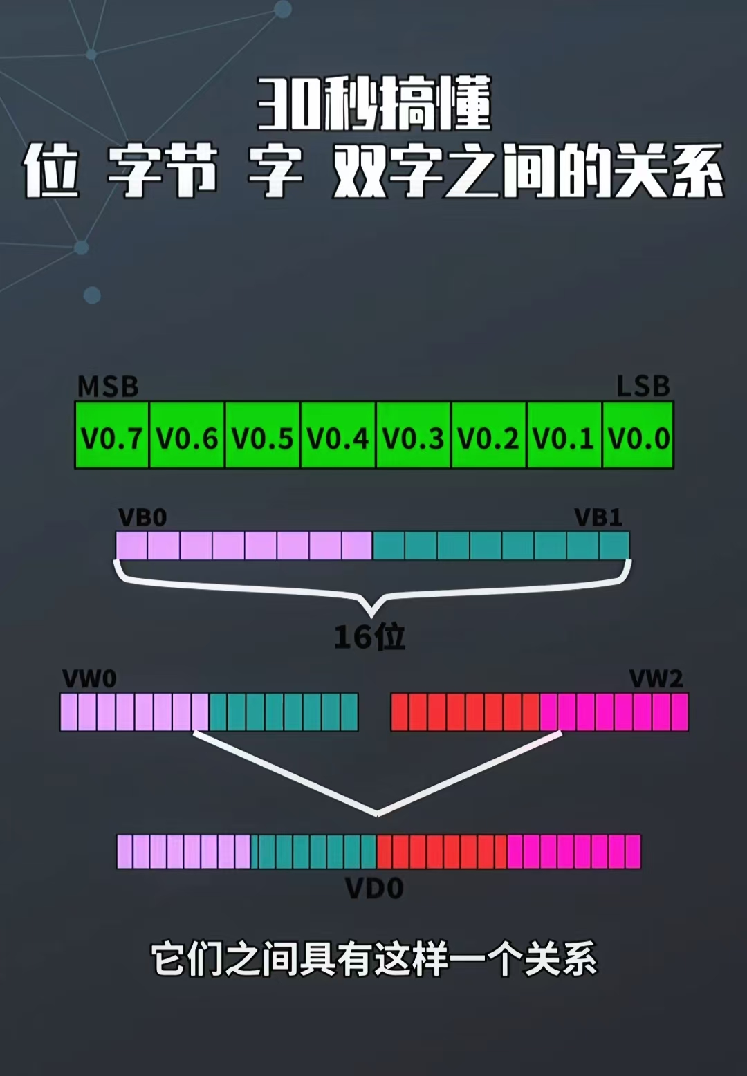
1. Bit: The Most Basic Electronic Switch
- Definition1 bit = 1 binary digit, with only two states: 0 (off) and 1 (on), equivalent to asingle light switch.
- Application in PLCUsed to represent discrete signals, such as buttons (I0.0), indicator lights (Q0.0), and intermediate flags (M0.0).
- Key FeatureCannot store data independently; must be combined into larger units.
2. Byte: A Drawer of 8 Switches
- Definition1 byte = 8 bits (1Byte = 8Bit), equivalent to8 switches in 1 drawer, capable of storing integers from 0 to 255.
- Application in PLCStores 8-bit sensor data (e.g., temperature -25℃ to +25℃ from an 8-bit AD conversion), ASCII characters (1 character = 1 byte).
- Address RepresentationSiemens IB0 (input byte 0, containing I0.0 to I0.7), Mitsubishi B0 (byte register).
3. Word: A File Cabinet of 2 Drawers
- Definition1 word = 2 bytes = 16 bits (1Word = 2Byte = 16Bit), equivalent to2 drawers forming 1 file cabinet, capable of storing integers from 0 to 65535.
- Application in PLCCurrent value of counters (e.g., the current value of C0 stored in a word register), 16-bit analog values.
- Address RepresentationSiemens IW0 (input word 0, containing IB0 and IB1), Mitsubishi D0 (data register, default 16 bits).
4. Double Word: A Warehouse of 4 Drawers
- Definition1 double word = 2 words = 4 bytes = 32 bits (1DWord = 2Word = 4Byte = 32Bit), equivalent to4 drawers forming 1 warehouse, capable of storing integers from 0 to 4294967295 (unsigned) or floating-point numbers.
- Application in PLCLarge value accumulation (e.g., total production on a production line), 32-bit floating-point numbers (e.g., temperature 25.5℃ stored in IEEE 754 format).
- Address RepresentationSiemens ID0 (input double word 0, containing IW0 and IW2), Mitsubishi D0+D1 (two consecutive D registers forming a double word).
Relationship Mnemonic: 8 bits make a byte, 2 bytes make a word, a double word is 32 bits, and data types must match.
2. Addressing in PLCs: How Different Brands Store Data
1. Siemens PLC: A Flexible Modular Storage Rack
- Address FormatExpressed as area + type + number, supporting mixed addressing of bits, bytes, words, and double words.
- Bit: I0.0 (input bit 0), Q0.1 (output bit 1), M1.2 (intermediate bit 2)
- Byte: IB0 (input byte 0, containing I0.0 to I0.7), MB10 (intermediate byte 10)
- Word: IW2 (input word 2, containing IB2 and IB3), MW20 (intermediate word 20)
- Double Word: ID4 (input double word 4, containing IW4 and IW6), MD30 (intermediate double word 30)
- AdvantagesAllows selection of the smallest unit as needed (e.g., reading the state of a specific bit of a single sensor).
2. Mitsubishi PLC: Fixed Shelf Storage
- Address FormatBits and words are represented separately, with no native support for bytes/double words, requiring conversion through instructions.
- Bit: X0 (input bit 0), Y1 (output bit 1), M2 (intermediate bit 2)
- Word: D0 (data register, 16 bits), T0 (current value of timer, 16 bits)
- Double Word: Requires two consecutive D registers (e.g., D0 and D1 form a 32-bit double word)
- NoteReading byte data requires using the “MOV” instruction to split (e.g., the high 8 bits of D0 stored in B0).
3. Brand Comparison Table
| Data Unit | Siemens (S7-1200) | Mitsubishi (FX5U) | Storage Range (Unsigned) |
|---|---|---|---|
| Bit | I0.0, Q0.1, M0.2 | X0, Y1, M2 | 0~1 |
| Byte | IB0, MB10 | B0 (requires instruction) | 0~255 |
| Word | IW2, MW20 | D0 | 0~65535 |
| Double Word | ID4, MD30 | D0+D1 | 0~4294967295 |
3. Data Type Pitfall Guide: Don’t Let Unit Errors Ruin Your Program
1. Signed vs Unsigned: Don’t Let Negative Numbers Disappear
- Unsignedbyte (0
255), word (065535), double word (0~4294967295), can only store positive numbers. - SignedINT (16 bits, -32768
32767), DINT (32 bits, -21474836482147483647), can store negative numbers (the highest bit is the sign bit). - CaseThe temperature sensor measures a range of -10℃ to 50℃, requiring the INT type (16-bit signed); using WORD (unsigned) would lose negative number information.
2. Floating Point: The Hidden Password of the Decimal Point
- Definition32-bit double word stores in IEEE 754 format, can represent decimals (e.g., 25.5℃).
- Pitfalls in PLCSiemens ID0 directly corresponds to REAL type, while Mitsubishi requires the “FLT” instruction to convert double word to floating point.
- Byte Order IssuesDuring Modbus communication, 32-bit floating point numbers may have “big-endian/little-endian” modes (e.g., Siemens big-endian, Mitsubishi little-endian), requiring the “SWAP” instruction to exchange bytes.
3. Address Overlap: Don’t Let Data Clash
- Error CaseSimultaneously using Siemens “IB0” (byte) and “IW0” (word) will cause data overwrite.
- RuleWord addresses must start from even bytes (e.g., IW0, IW2), and double word addresses must start from multiples of 4 bytes (e.g., ID0, ID4).
4. Practical Cases: Bridging Theory to Application
Case 1: Implementing Motor Interlock with Bit Operations
Requirement: The motor forward (Q0.0) and reverse (Q0.1) cannot start simultaneously.Programming Logic:
- Forward button I0.0 → M0.0 set, M0.1 (reverse flag) normally closed → Q0.0 output
- Reverse button I0.1 → M0.1 set, M0.0 normally closed → Q0.1 outputKey: Use normally closed contacts of M0.0 and M0.1 to achieve interlock, each flag is 1 bit of data.
Case 2: Storing Counter Values with Words
Requirement: Count the number of products, maximum value 5000.Programming Logic:
- Photoelectric sensor I0.2 triggers once, counter C0 current value (16-bit word type) adds 1
- When C0 ≥ 5000, Q0.2 (alarm light) turns onNote: The current value of C0 is stored in a word register (e.g., MW10), range 0~65535, meeting the 5000 requirement.
Case 3: Storing Floating Point Temperature with Double Words
Requirement: The PLC reads temperature transmitter data via Modbus (25.5℃, 32-bit floating point).Steps:
- Read Modbus holding registers 40001 and 40002 (2 16-bit words)
- Siemens: Combine IW2 and IW4 into ID2 (double word), directly convert to REAL type
- Mitsubishi: Convert D0 and D1 to floating point using the “FLT” instructionResult: ID2 or D0 stores the IEEE 754 format data for 25.5.
5. Why Are These Four Units So Important?
- Fault StatisticsAccording to ABB’s technical white paper,30% of PLC program errors arise from misuse of data types (e.g., using WORD to store negative numbers, address overlap).
- Efficiency ImprovementCorrectly selecting units can reduce50% of debugging time (e.g., using bit operations instead of word operations saves memory).

↓
Long press the QR code to register online