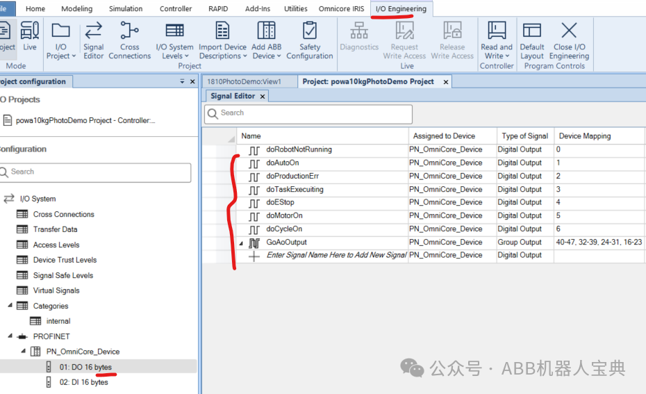
1. The new ABB RW7 robot has migrated the system signals to the controller. When in use, predefined DI/DO signals can be associated with it to allow the external PLC to start the robot. The specific steps are as follows:1.1. Predefine the DI/DO signals in the I/O engineering tool, as detailed in the configuration of the collaborative robot Powa’s Profinet slave.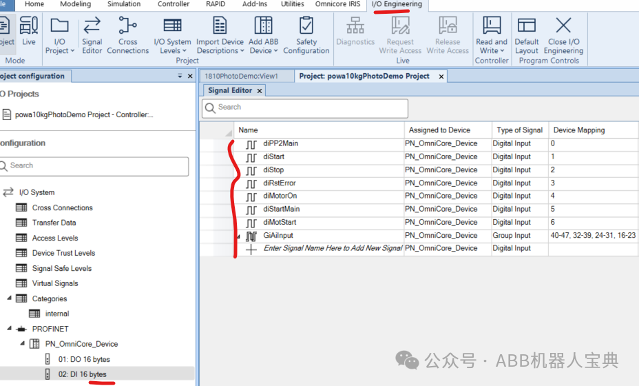
 1.2. Associate the defined DI/DO signals with the system signals.
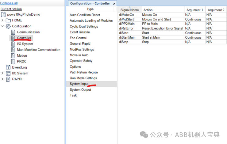
 2. The new RW7 system input signal definitions are as follows:
| Backup | Backup |
| Collision Avoidance | Collision prediction (The Coll-PredSafety Distance in MotionSystem determines the collision distance (in meters)) |
| Disable Backup | Prevent backup |
| Enable Energy Saving | Enable controller energy saving |
| Interrupt | Interrupt |
| Limit Speed | Speed limit (to be used with command SpeedLimAxis or SpeedLimCheckPoint) |
| Load | Load program (must be in automatic mode) |
| Load and Start | Load program and execute from the beginning |
| Motors Off | Motors off |
| Motors On | Motors on |
| Motors On and Start | Power on motors and start program |
| PP to Main | Program pointer to main program |
| ProfiSafe Operater Acknowledge | Profisafe communication operation confirmation |
| Quick Stop | Quick stop |
| Reset Execution Error Signal | Reset execution error signal |
| Set Speed Override | Set speed percentage |
| SimMode | Simulation mode |
| Start | Start program |
| Start at Main | Start from main program |
| Stop | Stop program |
| Stop at End of Cycle | Stop program after main program cycle ends |
| Stop at End of Instruction | Stop program after current instruction ends |
| System Restart | Restart system |
| Trust Revolution Counter | Revolution counter confirmation updated (only for IRB365) |
| Verify Local Presence | Verify local presence (used when there is no TPU, requires changing the value quickly 3 times within 40 seconds during the first login) |
| Verify Move Robot In Auto | Verify local presence and provide a 30-second opportunity to move the robot in automatic mode |
| Write Access | Write permission |
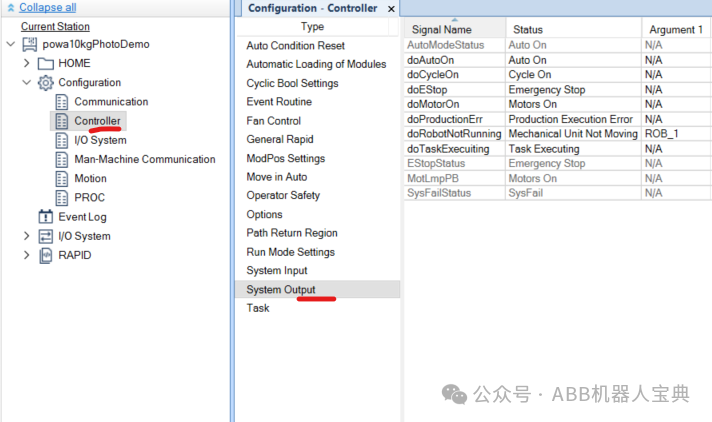
The system output signal definitions are as follows:
| Absolute Accuracy Active | Absolute accuracy activation status |
| Auto On | Robot in automatic mode |
| Backup Error | Backup error |
| Backup in progress | Backup in progress (system sets to 1 during backup, sets to 0 when finished) |
| Collision Avoidance | Collision prediction signal output |
| Cycle On | Program in cycle |
| Emergency Stop | Robot in emergency stop state |
| Energy Saving Blocked | System energy saving blocked state output |
| Execution Error | Execution error (this signal is output when there is no error handler processing the current error) |
| Limit Speed | Speed limit state output (speed has been reduced to the commanded speed) |
| Mechanical Unit Active | Mechanical unit activation status |
| Mechanical Unit Brakes Applied | Brake status when the motor is on (1 when brake is released, 0 when brake is applied) |
| Mechanical Unit Not Moving | Mechanical unit not moving |
| Motion Supervision On | Collision monitoring enabled state (robot must be in MotorON state) |
| Motion Supervision Triggered | Collision monitoring has been triggered |
| Motors Off | Motors off (1-second frequency pulse signal) |
| Motors Off State | Motors off state |
| Motors On | Motors on (1-second frequency pulse signal) |
| Motors On State | Motors on state |
| Path Return Region Error | Path return region error (set to 1 when the robot deviates too far from the program path) |
| Power Fail Error | Power on failure error |
| PP Moved | Pointer has been moved (when the parameter is set to Pulse, the pointer moves once, and the signal jumps once) |
| Production Execution Error | Execution error during operation (including program execution errors, collisions, or SysFail/SysHalt/SysStop RapidBlocked) |
| Revolution Counter Lost | Revolution counter lost |
| Robot In Trusted Position | Robot has reached position |
| Run Chain OK | Run safety chain OK (generally effective in automatic mode) |
| SimMode | Simulation mode output |
| Simulated I/O | IO signal in simulation mode (if any signal is in simulation mode, it is set to 1) |
| SMB Battery Charge Low | SMB battery low (monitored every 10 hours) |
| Speed Override | Speed percentage output (associated with group output signals that can be passed to PLC) |
| Stop from client | Client stop output (when using TPU or robot studio to execute stop operation, this signal will pulse for 1 second) |
| System Input Busy | System input busy |
| TaskExecuting | Task executing (not counted during path recovery) |
| TCP Speed | Actual TCP speed output (associated with analog output signals that can be passed to PLC) |
| TCP Speed Reference | TCP programming speed output (associated with analog output signals that can be passed to PLC) |
| Write Access | Write permission status output |
3. The process for the external PLC to start the robot is as follows:Switch the robot to automatic mode on the teach pendant –> PLC triggersdiPP2Main(2S pulse) –> PLC triggersdiMotorOn(2S pulse) –> PLC triggersdiStart(2S pulse) to start the program