(Thanks to everyone for your likes and appreciation. If this article resonates with you, please “like” and “recommend” it, thank you all!)
Task Introduction
In the field of industrial control, sequential control is one of the core skills of PLC programming, especially suitable for equipment that operates in a fixed process, such as machine tool processing and assembly lines. The Siemens S7-1200, as a main controller for small to medium automation scenarios, can perfectly implement complex sequential logic with its flexible programming methods. This article takes the dual-head drill as a typical case, guiding you step-by-step from task analysis to functional diagram design and then to ladder diagram programming, helping you master the core logic of sequential control.
01
—
Task Assignment
Device Background
A certain drill uses two drill heads to process two holes in a workpiece simultaneously, achieving a fully automated processing flow through PLC control, involving actions such as workpiece clamping, drill head downward/upward movement, and limit detection.
Control Requirements
- Initial State: Both drill heads are at the top position, with limit switches SQ1 (Drill Head 1) and SQ3 (Drill Head 2) both “ON”; the workpiece is in an unclamped state.
- Start Process: After the operator places the workpiece, they press the start button I0.0, and the system begins automatic operation.
- Operation Steps:
- Step 1: The workpiece is automatically clamped (proceed to the next step after clamping is complete);
- Step 2: Both drill heads move downward simultaneously (drilling);
- Step 3: When Drill Head 1 moves down to limit switch SQ2 (“ON”), it stops moving down and starts moving up; when Drill Head 2 moves down to limit switch SQ4 (“ON”), it stops moving down and starts moving up;
- Step 4: Drill Head 1 stops moving up when it reaches SQ1 (“ON”); Drill Head 2 stops moving up when it reaches SQ3 (“ON”);
- Step 5: When both drill heads return to the upper limit (SQ1 and SQ3 are both “ON”), the workpiece is automatically released;
- Step 6: After the workpiece is released, the system returns to the initial state, waiting for the next start.

02
—
Task Implementation
1. Draw Hardware Circuit Diagram

Define PLC Inputs (Detection Signals) and Outputs (Execution Signals) Based on Control Requirements:
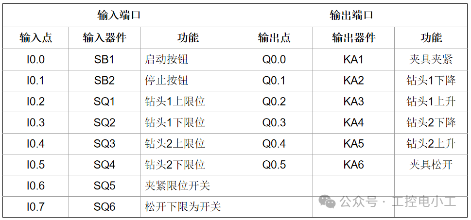
2. Functional Diagram (SFC) Design
The functional diagram is the “skeleton” of sequential control, intuitively expressing logic with steps (S), transition conditions (X), and actions (Y), dividing the drilling process into 6 key steps (sequences), clarifying the “execution actions” and “transition conditions” for each step:
Initial StepS0:Q0.0 (clamping) = OFF, Q0.1~Q0.4 (drill head actions) = OFF; only when I0.0 (start) = ON, transition to S1.
StepS1:Q0.0 = ON (workpiece clamped); set clamping delay T37 (e.g., 2 seconds), transition to S2 when T37 = ON.
StepS2:Q0.1 = ON (Drill Head 1 downward), Q0.3 = ON (Drill Head 2 downward); when I0.2 (SQ2) = ON, Drill Head 1 prepares to move up; when I0.4 (SQ4) = ON, Drill Head 2 prepares to move up.
StepS3:Q0.1 = OFF, Q0.2 = ON (Drill Head 1 upward); Q0.3 = OFF, Q0.4 = ON (Drill Head 2 upward); when I0.1 (SQ1) = ON and I0.3 (SQ3) = ON, transition to S4.
StepS4:Q0.0 = OFF (workpiece released), Q0.2 = OFF, Q0.4 = OFF; set release delay T38 (e.g., 2 seconds), return to S0 when T38 = ON.
Based on the working steps of the drill, the following sequential functional diagram is drawn.

03
—
Task Implementation
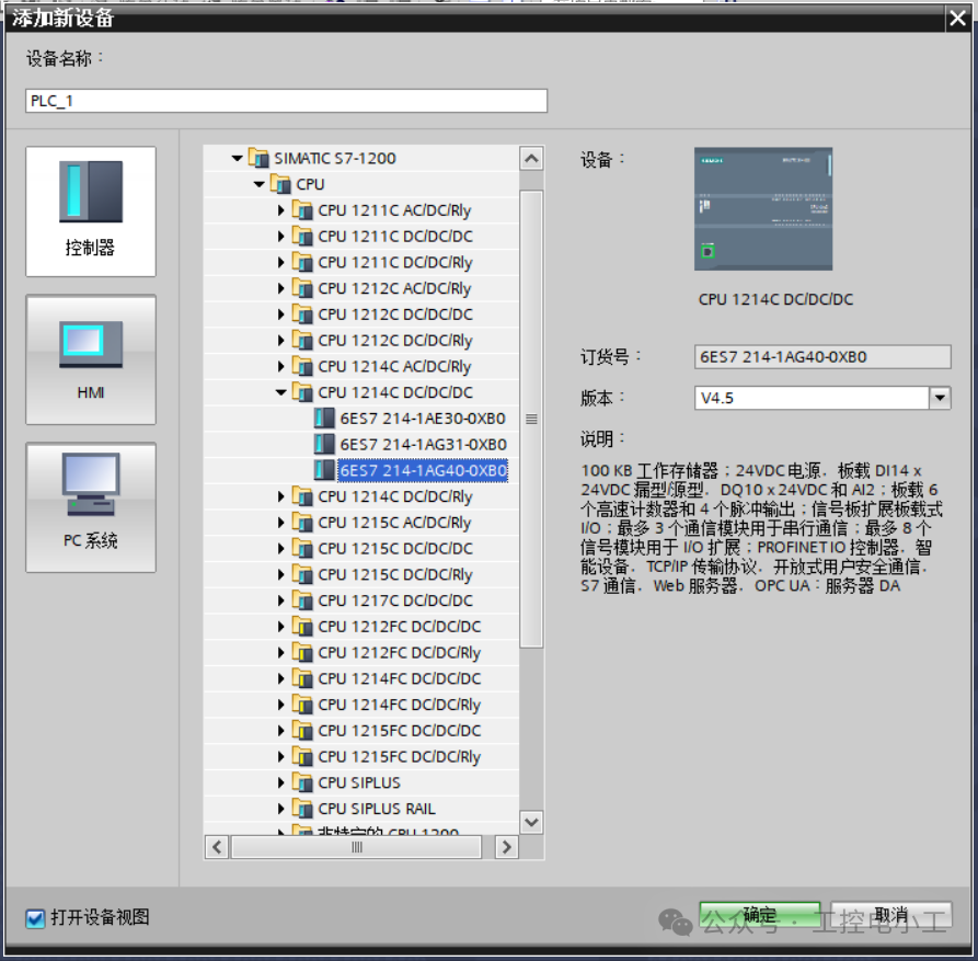
First, complete the device configuration, select to add a new device—controller—choose the CPU 1214C DC/DC/DC PLC, and select version V4.5 to match the physical device.
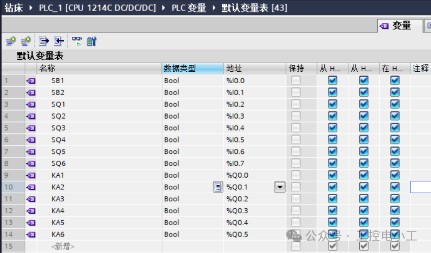
Create PLC variable table
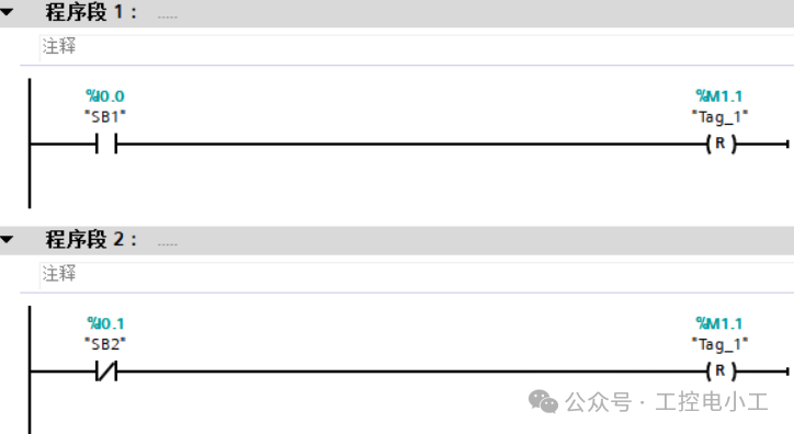
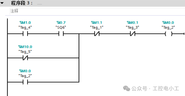
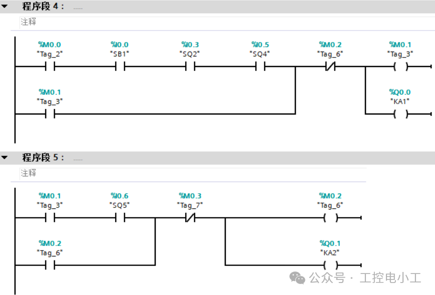
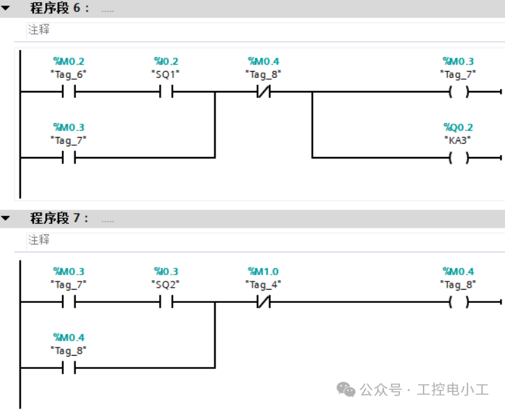
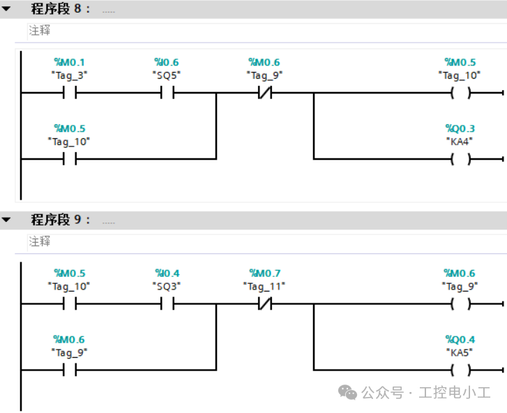
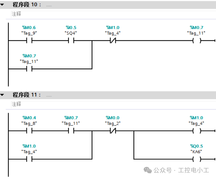
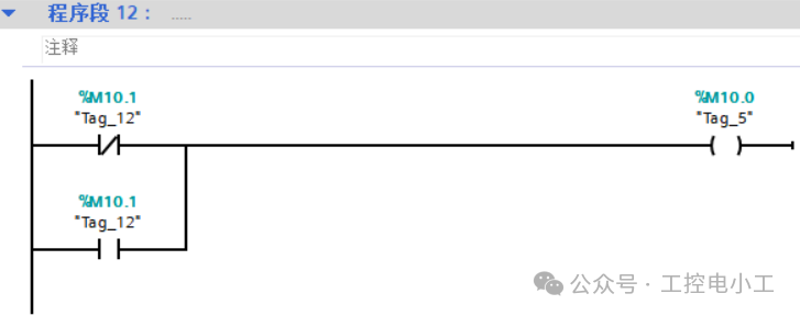
Based on the functional diagram, implement using Siemens S7-1200 ladder diagram (LAD), with the key logic as follows:
04
—
Task Acceptance
Testing Steps
-
Simulation Testing: Use PLC simulation software (such as TIA Portal’s PLCSIM) to simulate input signals and verify whether each step transition is correct:
- Press I0.0, observe whether Q0.0 is powered (clamping);
- After the delay, check whether Q0.1 and Q0.3 are powered (drill heads moving down);
- Trigger I0.2 and I0.4, check whether Q0.1 and Q0.3 lose power, and whether Q0.2 and Q0.4 are powered (moving up);
- Trigger I0.1 and I0.3, confirm that Q0.2 and Q0.4 lose power, and Q0.0 loses power (release);
- After release, check if it returns to the initial state.
-
On-site Debugging: Connect to the actual device, focusing on testing the reliability and continuity of limit switches to avoid logical errors due to mechanical delays.
1
END
1
Previous Reviews
How to Use the OB100 Startup Organization Block of Siemens PLC? Includes Typical Initialization Cases + Pitfall GuideTypical Application Cases of Time Interrupt Organization Block OB10 of Siemens S7-1200 PLCTypical Application Cases of Cycle Interrupt Organization Block of Siemens S7-1200 PLCTypical Applications of FB Multiple Backgrounds in Siemens PLC: Monitoring Operation of Multiple MotorsPractical Case: Achieving PROFINET Communication with Two S7-1200 PLCs, Detailed Steps Included, All Programs Provided for Easy ImplementationPractical Case | How to Control Cycle Color Lights with S7-1200, Complete Source Code Included, Easy to Replicate!Must-Know for Senior Electricians: Automatic Door Control with Siemens S7-1200 PLCMust-Know for Senior Electricians: Traffic Light Control at Intersections with Siemens S7-1200 PLCMust-Know for Senior Electricians: Automatic Assembly Line Control with Siemens S7-1200 PLCMust-Know for Senior Electricians: Automatic Mail Sorting Machine Control with Siemens S7-1200 PLC
If you like the articles from Industrial Control Electrician, please click on the business card to follow me! I will continue to share technical insights about PLCs and industrial robots!