 The timed lock machine is a “payment collection trick” in PLCs—it seems like just reading the time and calculating a password, but it actually sets a “time alarm” for the device: when the agreed date arrives, the machine locks automatically, and after the final payment is made, entering a password unlocks it, which is very convenient. Beginners can easily understand the PLC logic of “reading time, judging time, and locking the device” by following along.
1. Control Requirements for the Timed Lock Machine (Function Definition)
1. Time Reading: The PLC automatically obtains the local real-time and splits it into specific information such as year, month, day, hour, minute, and second;;
2. Timed Locking: Set a preset locking time; when the real-time exceeds this time, it automatically triggers the “program lock state” to lock the core functions of the device;
3. Dynamic Password: After locking, the PLC generates a dynamic password based on the current minute (changing every minute); only the correct password can unlock it;
4. Self-Locking State: Once the lock state is triggered, it remains self-locked until the correct password is entered, preventing failure after power loss and restart.
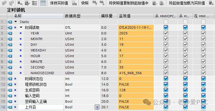
2. DB44 Point Table (Hardware and Data Correspondence)
3. 4 Steps to Program the Timed Lock Machine (Logic Breakdown))
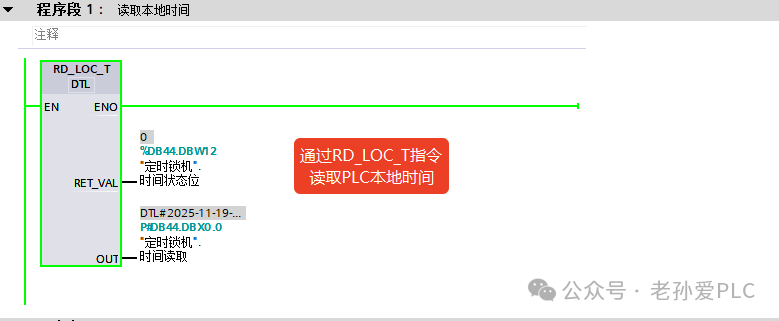
Step 1: Read PLC Local Time (Program Segment 1)
Core Logic: Use the<span><span>RD_LOC_T</span></span> instruction to read the PLC real-time and store it in a data block for later use..
Operation Steps:
1. Call the RD_LOC_T instruction (local time reading instruction), set the enable bit (EN) to 1 to trigger time reading;
2. Connect the OUT terminal of the instruction to “Time Read.Time” (DBX0.0) to store the real-time in this DTL type variable;
3. Connect the RET_VAL terminal to “Time Status Bit” (DBX12.0), where 0 indicates normal time reading and non-zero indicates an error in reading.
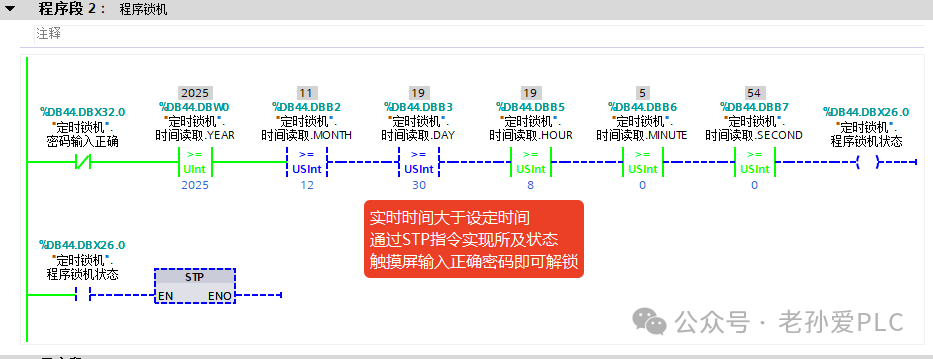
Step 2: Timed Lock Trigger Logic (Program Segment 2)
Core Logic: Compare the real-time with the preset locking time; if exceeded, trigger the lock state.
Operation Steps:
1. Connect the normally closed contact of “Password Input Correct” (DBX32.0) with the year, month, day, hour, minute, and second of the real-time to perform equality checks with the preset locking time, forming a triggering condition;;
2. When the real-time ≥ preset locking time and the password has not been verified, trigger the STP instruction (set lock state) to set “Program Lock State” (DBX26.0) to TRUE, locking the device functions;
3. Once “Program Lock State” is set to TRUE, it remains self-locked until the password is verified.
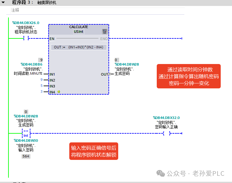
Step 3: Generate Dynamic Unlock Password (Program Segment 3)
Core Logic: Generate a dynamic password that changes every minute based on the current minute.
Operation Steps:
1. Call the CALCULATE instruction, connecting “Time Read.MINUTE” (DBB6) to IN1, preset parameter 9 to IN2, 5 to IN3, and 3 to IN4;
2. Set the calculation formula of the instruction to OUT = ((IN1+IN3)*(IN2 – IN4)), which means (minute number + 5)*(9 – 3), and store the result in “Generated Password” (DBW28);
3. Since the minute number changes every minute, the password will automatically update, preventing fixed passwords from being cracked.
Step 4: Password Verification Unlock Logic (Continuation of Program Segment 3)
Core Logic: Compare the input password with the generated password; if they match, unlock the machine state.
Operation Steps:
1. Perform an equality check between “Generated Password” (DBW28) and “Input Password” (DBW30);
2. When both are equal, trigger “Password Input Correct” (DBX32.0) to TRUE, while resetting “Program Lock State” (DBX26.0) to unlock the device;
4. Core Logic of the Timed Lock Machine (2 Points for Beginners)
1. Time Determination is Fundamental: The time read by RD_LOC_T must be broken down into specific variables such as year, month, day, etc., to make precise comparisons with the preset time; this is a universal logic for all timed projects;
2. Dynamic Passwords Prevent Cracking: Using the minute number to generate a password that changes every minute is more secure than a fixed password, and the calculation logic is simple, allowing beginners to quickly modify parameters to adapt to different devices.
Learn technology solidly, improve a little every day! Do my best to help more people!