1. Introduction
UART, full name Universal Asynchronous Receiver/Transmitter, translated as Universal Asynchronous Transceiver.
The emergence of serial ports was around 1980, with data transmission rates of 115kbps~ 230kbps. Initially, serial ports were used to connect computer peripherals, typically connecting mice, external Modems, and old cameras and graphics tablets. Serial ports can also be used for interconnection and data transmission between two computers (or devices). Due to the fact that serial ports (COM) do not support hot swapping and have lower transmission rates, some new motherboards and most portable computers have begun to eliminate this interface. Currently, serial ports are commonly used in industrial control and measurement devices as well as some communication devices.
Almost all MCUs have a UART interface.
–from Baidu Encyclopedia
https://baike.baidu.com/item/Serial Interface
Whenever the term “serial port” is mentioned, it easily brings to mind terms like UART, USART, COM port, TTL/CMOS, RS-232, RS-422, RS-485. Among them:
-
UART, the name of the “serial port” timing protocol, defines the timing protocol for various signals;
-
USART, compared to UART, adds a synchronous signal, enabling ISO-7816 smart card interfaces;
-
COM port, in PC and other operating systems, distinguishes itself from USB and SATA interfaces as a serial interface, defining standards in operating systems;
-
TTL/CMOS, signal levels in embedded hardware systems;
-
RS-232, defines the electrical characteristics of signals based on UART
-
RS-422, defines the electrical characteristics of differential signal transmission based on RS-232
-
RS-485, defines half-duplex mode based on RS-422
2. Signal Lines
The naming of signal lines is based on the current terminal device.
Common signal lines for UART include:
RxD, the receiving pin of the current terminal device
TxD, the transmitting pin of the current terminal device
GND, the ground of the current terminal device
As mentioned, the naming of signal lines is marked based on the current terminal device, allowing for quick identification of connection sequences during manual wiring.
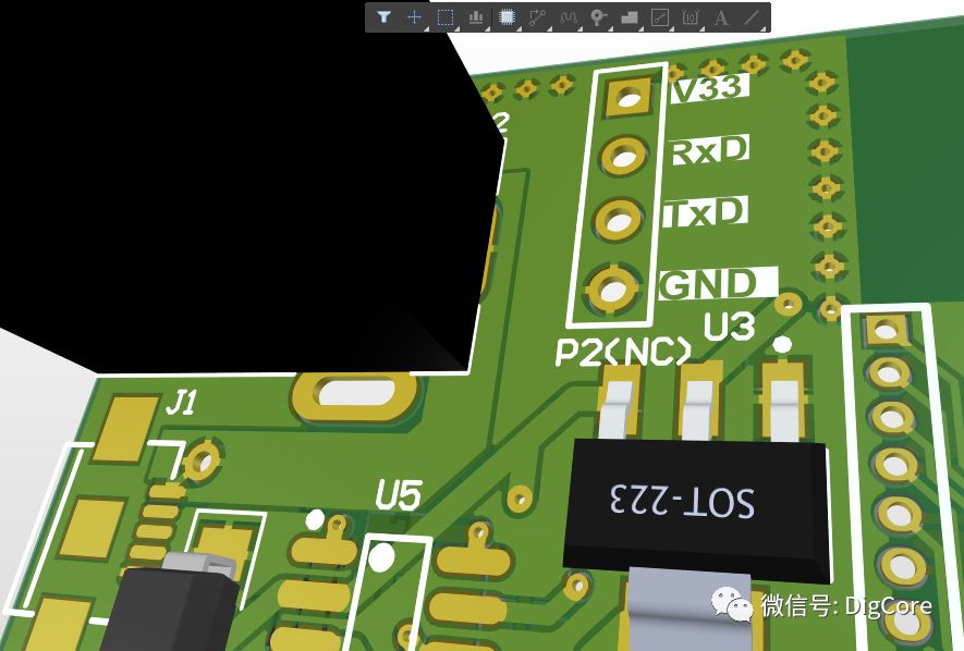
Generally, designers will add silk screen markings when designing PCBs for external connections, marking interface pins with the current terminal device’s pin information.
For example, a pin marked RxD should connect with the external UART interface TxD.
3. Signal Timing
When the signal line is idle, it is at a high level; when data is sent, the signal line marks the start of communication with a low level for 1 bit duration. During communication, the frame structure of a single byte on the signal line is as shown in the following figure:
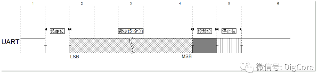
When the signal pin transmits each data, the electrical signal presented on the pin shows the change between high and low levels, corresponding to the logical “1” and “0” of each bit.
The structure of the UART frame, accompanied by start bits and stop bits, defines each byte of the transmitted data flow, implementing a start protocol. Additionally, a parity bit can optionally be inserted before the stop bit to verify the correctness of the data frame.
The following figure shows the common configuration parameters used during UART communication, corresponding to the timing of 8-N-1:
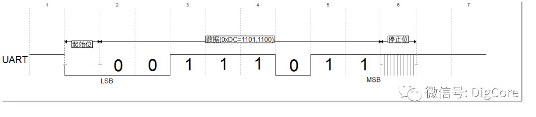
Configuration parameters (8-N-1): 8bit data, no parity bit, 1bit stop bit
4. Interface Configuration Items
When enabling the UART interface, both communicating parties must configure the same parameters for the interface to communicate correctly. The configurable parameters of UART include:
(1) Baud Rate:
Since UART is asynchronous communication, there is no synchronized clock CLK provided to the receiver during communication, making it impossible for the receiver to synchronously determine the width of each bit, and therefore unable to sample each bit correctly.Thus, the receiver must rely on setting the same baud rate parameters as the sender, allowing the receiver to sample and decode the signal pin accurately to determine whether each bit is “1” or “0, which is a characteristic of asynchronous communication.
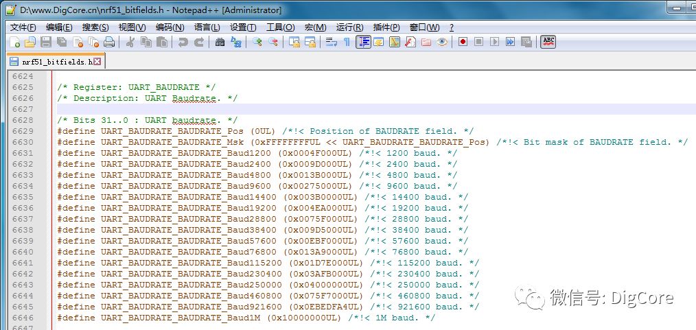
In various MCUs, common baud rate values include:
4800Bd, 9600Bd, 19200Bd, 115200Bd, unit Bd. Common code snippets include:
To understand baud rate, refer to Wikipedia
(https://en.wikipedia.org/wiki/Serial_port).
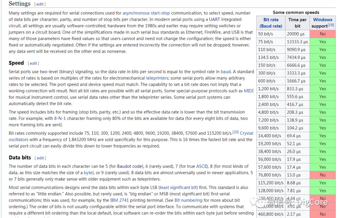
In the Wikipedia introduction, it can be seen that the value of baud rate directly derives the unit s/bit by taking the reciprocal of the unit of bit/s. Additionally, when capturing the waveform emitted by UART on an oscilloscope, it can be seen that the width of each bit is essentially the reciprocal of the baud rate within the allowable error range.
In the Baidu Encyclopedia entry on “Baud,” it states:
Modulation rate refers to the rate at which effective data signals modulate the carrier, that is, the number of times the carrier modulation state changes per unit time. It is a measure of the symbol transmission rate, 1 baud means transmitting 1 symbol per second, and through different modulation methods, multiple bits of information can be loaded onto a single symbol. The unit “baud” itself represents the number of modulations per second, and using “baud per second” as a unit is a common mistake.
It represents the change of signal, not the amount of data transmitted. It indicates the number of times the communication line state changes per second. If data is not compressed, baud equals the number of bits transmitted per second; if data is compressed, the number of bits transmitted per second is usually greater than the modulation rate, leading to potential confusion when using baud and bit/second interchangeably.
However, in modern practical use, in most cases, after configuring the baud rate of the MCU, observing the output signal, it is found that the baud rate equals the bit rate. This is because the transmitted symbols are 8bit data, thus the baud rate equals the bit rate.
If you obtain a board or a set of devices but do not have the source code, relying purely on hardware to capture the communication serial port data content, first use an oscilloscope to observe the width of each bit, then convert it to bit rate; at this point, the bit rate is essentially the baud rate. Using a serial port assistant module, download a serial port assistant on the PC side and set the matching baud rate for data capture.
For example, if the waveform captured is 116us/bit, the direct conversion yields: 1bit/116us = 1 bit/(116/1000000)s = 8620.68 bit/s; at this point, configuring the baud rate of the serial port assistant, connecting the serial port assistant module to the measured signal pin will enable the capture of serial data.
(2) Data Bits:
According to Wikipedia, the number of data bits can generally range from 5~9 bits, with different applications for each bit count:
-
5 bits are commonly used for Baudot code
-
7 bits are commonly used for ASCII characters
-
8 bits are used for most types of data and match with bytes(Byte)
-
6 bits and 9 bits are rarely used
Both transmitting and receiving parties must define the same width of data bits to accurately decode the transmitted data when sampling the signal pin.
As listed above, different data bit scenarios allow for the selection of suitable data for efficient transmission.
(3) Parity Bit:
The parity bit can be used during data transmission for the receiver to sample and decode the signal pin, checking the integrity and correctness of the data, ensuring effective exclusion of errors caused by unstable lines or external interference during communication.
The parity bit, as an optional configuration item, can be set in the following ways:
|
Configuration Method |
Function |
Remarks |
|
None |
No parity |
No parity bit in the data transmission frame structure |
|
Odd |
Odd parity |
If the number of “1”s in the data is odd, the parity bit is set to 0; If the number of “1”s in the data is even, the parity bit is set to 1. |
|
Even |
Even parity |
If the number of “1”s in the data is odd, the parity bit is set to 1; If the number of “1”s in the data is even, the parity bit is set to 0. |
|
Mark |
The parity bit is always “1” |
The parity bit is always “1” |
|
Space |
The parity bit is always “0” |
The parity bit is always “0” |
For the configuration of odd and even parity bits, it is easy to confuse the settings of odd and even parity; the following figure lists the timing diagrams of all parity configurations, where the transmitted data is the abbreviation of DigCore DC, which is hexadecimal 0xDC:
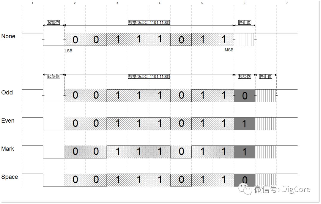
Comparing the various parity methods shown in the figure, simply put, odd parity (Odd-Parity) means that for the transmitted data 0xDC, in binary 11011100, there are 5 “1”s, which is an odd number of “1”s, thus the parity bit is set to “0”; at this point, the total number of logical “1”s is odd 5, achieving odd parity.
In short, the principle to ensure is that when odd parity is enabled, the total number of “1”s in the data plus the parity bit equals an odd number; when even parity is enabled, that total equals an even number.
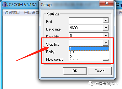
(4) Stop Bits:
Stop bits can be configured as 1bit, 1.5bit, and 2bit, and when configured as one of these, the signal pin maintains a high level for the corresponding bit duration.
The significance of the stop bit is to indicate the completion of data transmission, while providing reliable processing time for both parties during hardware operations.
(5) Flow Control:
Flow control, commonly known as “handshake”. The role of flow control is to notify the sender whether to continue with the next data transmission before data transfer occurs between devices with different processing capabilities. This application scenario is often seen in communication between computers and low-performance microcontrollers, as well as in data transmission between PC and printers, where the receiver’s buffer may be full or processing transactions slowly, necessitating flow control to inform the sender to wait before sending.
Flow control methods can be categorized into software and hardware.
Software flow control in UART communication requires only RxD, TxD, and GND lines; during data transmission, control is completed through code judgment and processing, with data interaction between both parties using control characters(ASCII codes from 0x00~0x0x1F, 0x7F) to complete control command interactions. Generally, some special characters are also defined under private protocols as control commands.
Hardware flow control means adding two more signal lines, RTS/CTS and DTR/DSR, based on the original RxD, TxD, and GND lines.
The first group of lines is RTS (Request to Send) and CTS (Clear to Send). When the receiver is ready to receive data, it sets the RTS line high to indicate readiness; if the sender is also ready, it sets the CTS high, indicating it will send data.
The second group of lines is DTR (Data Terminal Ready) and DSR (Data Set Ready). These lines are primarily used for Modem communication, indicating the status of the serial port and Modem communication.
For example, when the Modem is ready to receive data from the PC, it sets the DTR line high, indicating that the connection to the telephone line has been established. The DSR line is read as high, and the PC begins to send data. A simple rule is that DTR/DSR indicates system communication readiness, while RTS/CTS is for the transmission of individual data packets.
In practical applications, hardware methods are rarely used, primarily due to hardware cost consumption, and under current MCU performance, the UART FIFO buffer, MCU UART event interrupts, and other factors can adequately complete data reception and storage, which is sufficient for most application scenarios, thus hardware flow control is seldom utilized in many applications.
|
Signal |
Definition |
Function |
|
DTR |
Data terminal ready |
Data Terminal Ready |
|
DSR |
Data ready |
Data Set Ready |
|
RTS |
Request to send |
Request To Send |
|
CTS |
Clear to send |
Clear To Send |
This article has completed the description of the UART protocol basics, for details on the interface specifications under different electrical characteristics of UART, stay tuned for the next installment!
References:
“Serial Interface”@Baidu Encyclopedia
https://baike.baidu.com/item/Serial Interface
“Serial Port”@Wikipedia
https://en.wikipedia.org/wiki/Serial_port
“Baud”@Baidu Encyclopedia
https://baike.baidu.com/item/%E6%B3%A2%E7%89%B9/35033


www.digcore.cn
More technical content awaits you!
Long press the QR code to follow