The serial port enables reliable communication between two terminal devices, functioning as the transport layer in this process. This article focuses on the data protocol.
-
Similar Scenarios
Hey! Hey! This is Dong Guai! Please respond! Please respond! over!
Such dialogues are often seen in war-themed films when calling teammates through walkie-talkies or related wireless devices. First, the caller states the name of the other party, then identifies themselves, and concludes with the word over, indicating the end of the call.
Yes, that’s right! This is the start-stop protocol that plays a crucial role in serial communication!
The UART timing itself is a start-stop protocol, specific details can be found in the article titled “Embedded Hardware Communication Interface Protocol – UART (1) Protocol Basics”.
In fact, the serial port implements the transport layer in the data communication process, while the application layer manages the business logic of system functions, controlling various data content that needs to be sent and received.
The prerequisite for data parsing is that both parties in communication use a unified data frame format. Therefore, we will design a simple start-stop data frame format to ensure reliable communication between devices.
Many modern wireless modules use the UART interface for simplicity and ease of integration, employing AT commands for configuration and usage. Common examples include the ESP8266 WiFi module and the HC-05 Bluetooth serial module.
AT commands are characterized by being easy to interact with; when users send AT commands, they use ASCII characters. The processing of these commands is also handled as characters. The start-stop nature of such AT commands begins with the two characters “AT” and ends with the carriage return and newline characters “
”.
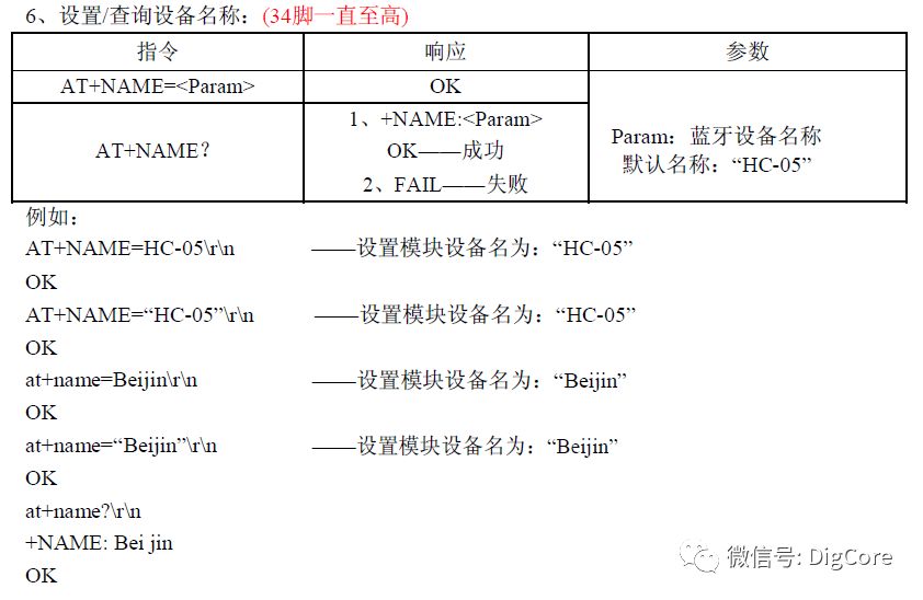
HC-05 Bluetooth Module Command Example
However, in project engineering, data in embedded devices is processed and handled in HEX (hexadecimal). If we design the frame structure based on AT commands, it will inevitably require processing the received pure data (hexadecimal) as characters during transmission.
For instance, a terminal device that functions for environmental monitoring may include temperature and humidity, light intensity, carbon dioxide concentration, and PM2.5 concentration. If it needs to send a temperature reading of 24℃, the collecting device will split the data 24 into two bytes for sending, as the ASCII character ‘2’ corresponds to hexadecimal 0x32 and ‘4’ corresponds to 0x34. Thus, this temperature data requires two bytes for transmission. The receiving end, upon receiving 0x32 and 0x34, will reverse lookup to obtain the original temperature data ’24’. This process illustrates one of the complexities of character processing.
Therefore, we will not consider using ASCII characters to form the frame structure.
-
Simplified Start-Stop Structure
The simplest frame consists of a start + end marker.
For example, 0x55 + Data Packet + 0xAA.
In a long stream of data, the receiving end will receive byte by byte and check for the presence of 0x55. If found, it will start storing data packets in the buffer until it receives the 0xAA data, indicating the completion of one frame of data reception.
This method is indeed quite simple, requiring minimal processing—just checking the start and end markers.
However, there is a significant issue: if the transmitted content also includes 0xAA as data, this 0xAA may not serve as an end marker, causing the program to prematurely terminate the reception process and failing to guarantee the complete reception of a data packet.
-
Add Length Limitation
Based on the simplified start-stop structure, we can add a field to indicate the length of the data packet.
For example, 0x55 + Length + Data Packet + 0xAA.
In this case, when the receiving end detects the 0x55 start marker, it will receive another byte as the “Length” field to continue receiving the remaining data based on this length.
With the length constraint, there is no longer a need for 0xAA as an end marker.
This type of interface still carries risks. For example, if the physical line experiences unknown interference during data transmission, causing the content to be corrupted, even if the receiving end receives all the expected data, it may still be incorrect.
-
Add Checksum
To address unknown errors that may occur during transmission, it is essential to perform a checksum on the data. We will add a field to indicate the checksum of the data content.
For example, 0x55 + Length + Checksum + Data Content + 0xAA.
The checksum is calculated using an algorithm on the data packet. The receiving end will receive all the data and then compute the checksum using the same algorithm to compare it with the received checksum to verify the accuracy of the data packet.
For checksum calculation, we will use the CRC-16 method, which has strong error detection capabilities and low overhead.
-
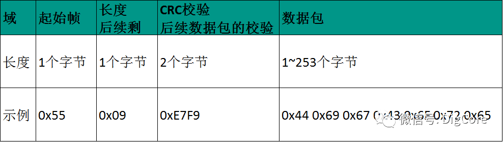
Design Protocol Frame Structure
In summary, based on the start-stop frame structure, we can design it as: 0x55 + Length + CRC Checksum + Data Packet.
Here, the frame header marker is represented by 0x55, which is one byte.
0x55 in binary is 01010101, resulting in a 50% duty cycle square wave on the UART physical line. Square waves are the easiest to measure and diagnose, allowing for stability and noise spike observations during actual waveform analysis.
Although 0xAA (binary 10101010) could also be used, the UART transmission starts with a 0 (start bit) and sends the least significant bit (LSB) first. The bit0 of 0xAA is already 0, while the bit0 of 0x55 is 1; thus, 0x55 is preferred for generating a square wave.
The length is represented by one byte, allowing for a maximum of 255 bytes in total for the CRC checksum + data packet.
The CRC checksum uses the CRC-16 algorithm, occupying 2 bytes, meaning the maximum data packet length is 253 bytes.
In conclusion, we arrive at the final start-stop frame structure:
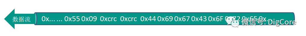
Next, we will begin designing the processing program.
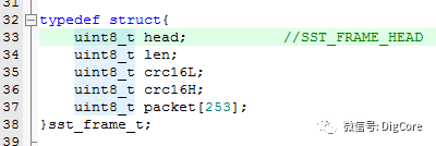
Based on the frame structure, we can define the following structure:
typedef struct{
uint8_t head;
uint8_t len;
uint8_t crc16L;
uint8_t crc16H;
uint8_t packet[253];
}sst_frame_t;
It is important to note that:
The maximum length of the packet data packet is set to 253 because len is of type uint8_t, with a maximum of 255, and the CRC checksum occupies 2 bytes, allowing for a maximum of 253 bytes in the data packet.
The CRC checksum uses the CRC-16 standard. The checksum is a uint16_t type, and during transmission, it is sent in LSB mode, thus defined as two uint8_t types to correctly handle endianness differences across platforms during source code migration.
Briefly describe the endianness differences in embedded device memory during structure definition and usage:
If the frame structure is defined as follows:
typedef struct{
uint8_t head;
uint8_t len;
uint16_t crc16;
uint8_t packet[253];
}sst_frame_t;
Assuming a calculated checksum result of 0xDC66, which is a uint16_t type. If this structure is directly used for data transmission, then:
On a LSB platform, the sending order of the data will be:
head, len, 0x66, 0xDC, packet[0], packet[1], …
Conversely, on an MSB platform, the sending order will be:
head, len, 0xDC, 0x66, packet[0], packet[1], …
Thus, using two uint8_t data types instead of uint16_t for defining the CRC checksum in the structure allows for seamless cross-platform data transmission without additional handling.
-
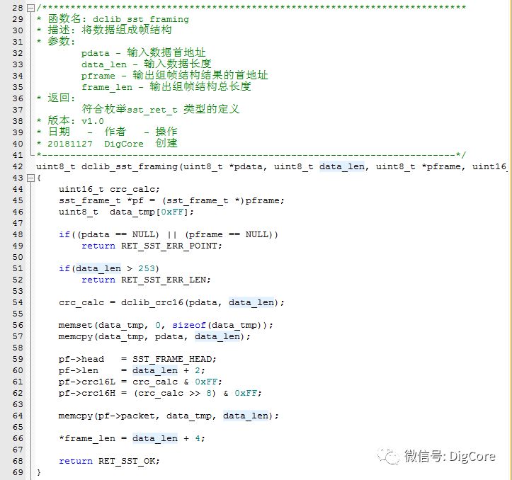
Constructing Frame Structure
When using start-stop for data transmission, the application layer data packet is framed, allowing for a complete data frame to be passed to the transport layer for transmission.
The construction process is essentially a “filling” process for the frame structure.
First, the CRC checksum of the data packet is calculated, followed by the “filling” process.
To prevent the application layer from passing in a data packet address that points to the same memory location as the filled result, the source data must be cached separately before the “filling” operation.
-
Parsing Frame Structure
Parsing the frame structure involves processing a long stream of data to extract the data packet.
The data being parsed comes from a circular buffer, which is used to read the available data.
Code Screenshot:
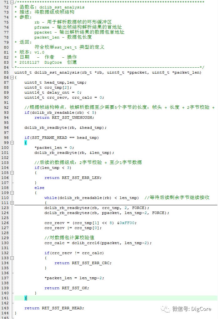
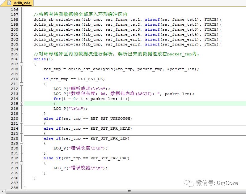
The parsing logic is as follows:
1. Ensure that the circular buffer has enough data for one frame structure; otherwise, return an insufficient data error.
2. Next, read one byte to check if the frame header marker is 0x55; if not, return a frame header error.
3. Read another byte as the frame length data, ensuring that the length is at least 3 bytes (2 bytes for CRC checksum + at least 1 byte for the data packet); otherwise, return a frame length error.
4. If the length data indicates that the readable amount in the circular buffer is less than the length value, this may indicate an abnormality during transmission, or the other device’s serial port is too slow to complete the transmission. In this case, a suitable delay should be implemented; if it times out, return a frame length error.
5. Continue to read 2 bytes as the CRC checksum, noting that crc16L is received first, which is the least significant byte.
6. Next, read the data packet, where the length should be the frame length data minus 2 bytes.
7. Finally, calculate the CRC checksum for the data packet and compare it with the received checksum; if they do not match, return an error checksum code.
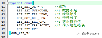
The function returns values corresponding to the following enumerated error codes:
-
Data Source Being Parsed
You may still wonder, where does the data source for parsing come from? When is the data written into the circular buffer?
Refer to the previous article “Embedded Hardware Communication Interface – Using RingBuffer to Handle Data (2) Detailed Design Process,” which discusses writing one byte into the circular buffer. However, dclib_ringbuffer belongs to the application library module layer. If we directly place dclib_rb_writebyte in the serial port receive interrupt, it disrupts the system architecture, complicating maintenance and migration of the project code. Therefore, we adopt a callback function approach.
Embedded developers know that when using official libraries, they often need to implement callback functions to register them with the library or driver layer, allowing the library or driver to invoke these functions during execution.
Following this logic, we also adopt a callback function to write the data received from the serial port into the circular buffer.
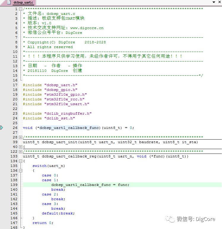
Callback function implementation source code screenshot:
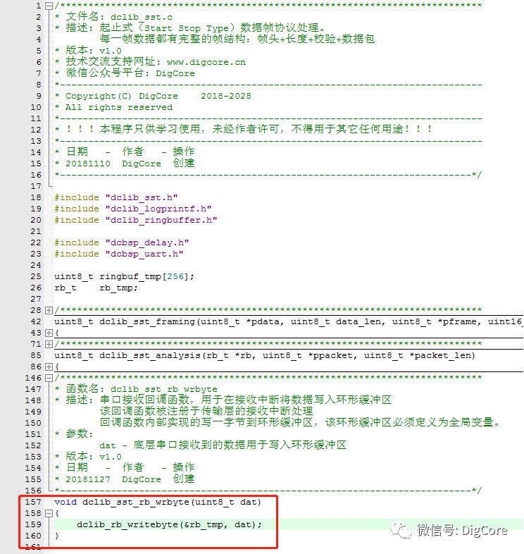
In fact, it merely calls the write one byte function dclib_ringbuffer dclib_rb_writebyte, where the parameter dat is the data received from the serial port.
With the callback function, we also need to pass its address to the underlying driver, which is known as the “registration” process. The registration interface is implemented in the firmware board-level interface layer for the serial port module, using the function dclib_uart_callback_reg:
I’ve digressed; I won’t delve deeper into callback functions here.
In summary, the execution process of writing one byte into the circular buffer occurs within the callback function. When the serial port receive interrupt is triggered, it will execute the registered callback function address to write one byte of data into the circular buffer. This approach preserves the layered architecture of the project code, facilitating maintenance and migration!
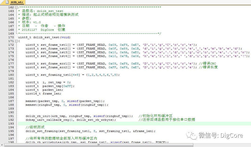
To reduce length, I will finally share a portion of the test code:
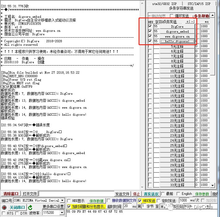
Finally, here are the parsing results from the serial port during debugging:
The explanation of the start-stop frame structure may seem a bit rushed, and the article is slightly lengthy. Key technical points were not elaborated in detail; further planning will be done for separate introductions!
Next, based on this frame structure, we will discuss how to design the application layer interaction commands in the data packet. Stay tuned for the next installment!
“ASCII”@Baidu Encyclopedia
https://baike.baidu.com/item/ASCII
“CRC”@Baidu Encyclopedia
https://baike.baidu.com/item/CRC/1453359
“CRC Open Source Project”@github
https://github.com/lammertb/libcrc

Long press the QR code to followDigCore
Follow the public account and send a message:
Download&StartStopType
Get this articlePDF Original Text or Source Code Download Link
★★★★★Recommended Articles:
“Quick Development of MQTT (1) MQTT from the Perspective of Electronic Engineers”
“Quick Development of MQTT (2) Introduction to MQTT”
“Building an MQTT Client – The Clearest MQTT Protocol Architecture”
“Building an MQTT Server – The Fastest Way to Validate Your Developed Client”
★★★★★Related Articles
“Embedded Hardware Communication Interface Protocol – UART (1) Protocol Basics”
“Embedded Hardware Communication Interface Protocol – UART (2) Standards Under Different Electrical Specifications”
“Embedded Hardware Communication Interface Protocol – UART (3) Quick Use of Serial Ports and Applications”
“Embedded Hardware Communication Interface – Using RingBuffer to Handle Data (1)”
“Embedded Hardware Communication Interface – Using RingBuffer to Handle Data (2) Detailed Design Process”
★★★★★Further Reading
“[Hardware Circuit] AltiumDesigner18 Rule Check Meanings”
“[Hardware Circuit] Basic Principles and Application Cases of N-channel and P-channel MOSFETs”


www.digcore.cn
More technical content awaits you!
Long press the QR code to follow