Recently, I saw some netizens discussing whether ‘CAN is more difficult than UART’ in a technical group. Some netizens said CAN is very simple, while others said CAN is very difficult.
In fact, whether it is difficult or not mainly depends on your perspective. Some netizens may have a good foundation and have studied CAN, so they might find it simple.However, for beginners with a poor foundation, CAN is indeed much more difficult than UART.
Here, I will share some basics of CAN bus for beginners. Compared to UART, the content is indeed much more extensive. As for whether CAN is more difficult than UART, you will have the answer after reading this.
CAN bus is a type of asynchronous communication, so there is a communication baud rate, and this baud rate generator is located inside the CAN controller. We do not need to understand how it is generated, but we need to understand its meaning. This section explains the following two points for beginners.
1. Asynchronous Communication
In serial communication, there are mainly asynchronous and synchronous communications.
Synchronous Communication: Communication where devices transfer data through synchronization signals (CLK clock) is called synchronous communication. For example, I2C and SPI communications have a clock signal, and actually, USART in STM32 also has synchronous capabilities, but most of us only use its asynchronous function.
Asynchronous Communication: Simply put, it is when communication devices send and receive data at agreed times. This timing will determine the baud rate discussed in this section.
Many engineers have not thoroughly understood what baud rate is, so I will briefly explain its meaning in conjunction with UART baud rate.
In electronic communication, baud (Baud) refers to the modulation rate, which indicates the rate at which effective data signal modulates the carrier, i.e., the number of times the carrier modulation state changes per unit time. It is a measure of the symbol transmission rate, 1 baud means transmitting 1 symbol per second.
UART transmits 240 characters per second, and each character format contains 10 bits (1 start bit, 1 stop bit, 8 data bits), so the baud rate is 240Bd, and bit rate is 10 bits * 240 characters/second = 2400bps.
From the description above, we can summarize:
Bit Rate: The number of binary bits transmitted per unit time;
Baud Rate: The number of symbols transmitted per unit time;
Only when each symbol represents one bit of information can the baud rate and bit rate be equal in value, but their meanings are different.
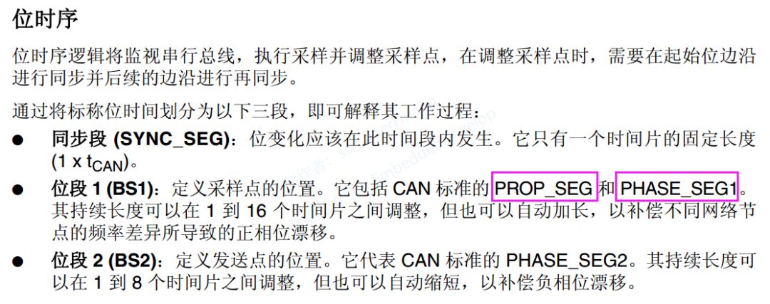
The baud rate discussed above is determined by the bit timing discussed in this section. In the CAN standard, one bit can be divided into 4 segments:
-
Synchronization Segment (SS)
-
Propagation Time Segment (PTS)
-
Phase Buffer Segment 1 (PBS1)
-
Phase Buffer Segment 2 (PBS2)
These segments are composed of the smallest time unit called Time Quantum (Tq).
One bit is divided into 4 segments, and each segment is composed of several Tq, which is called bit timing.
In the STM32 reference manual, the bit timing is divided into three segments, but it combines the propagation segment and bit segment 1 together, as shown in the following figure:
How many Tq a bit consists of, how many Tq each segment consists of, etc., can be set arbitrarily to determine the bit timing. By setting the bit timing, you can determine the transmission baud rate:
These parameters will be configured during programming, thus determining the communication baud rate.
Regarding synchronization, there are hardware synchronization, re-synchronization, and other operations. But beginners do not need to understand too much; mastering the basic content above is sufficient. For more information on bit timing, you can refer to the ISO 11898 standard.
Frame Types and Format Description
CAN bus communicates through the following 5 types of frames:
Data Frame: A frame used to send data from the sending unit to the receiving unit.
Remote Frame: A frame used by the receiving unit to request data from the sending unit with the same ID.
Error Frame: A frame used to notify other units of an error when an error is detected.
Overload Frame: A frame used by the receiving unit to notify that it is not ready to receive yet.
Frame Interval: A frame used to separate data frames and remote frames from the previous frame.
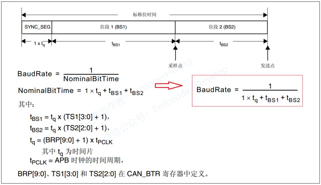
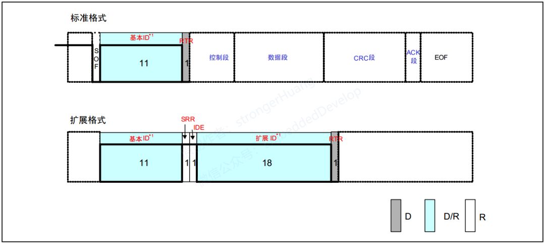
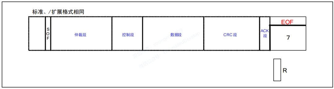
Data Frames and Remote Frames have both standard format and extended format. The standard format has an 11-bit identifier ID, while the extended format has a 29-bit ID.
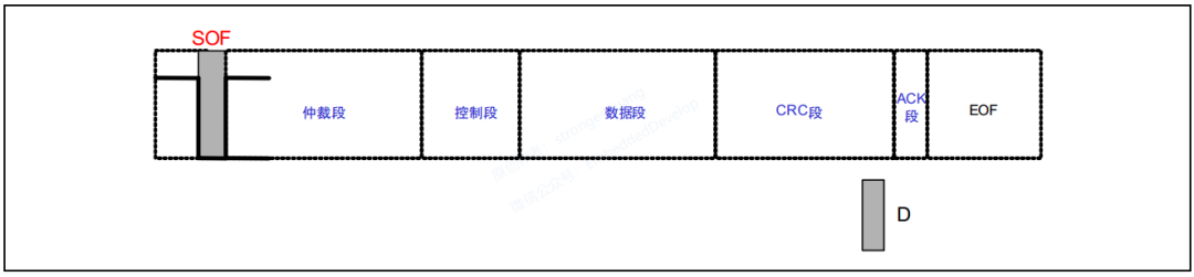
The data frame consists of 7 segments:
Indicates the segment where the data frame starts.
Indicates the segment that represents the priority of the frame.
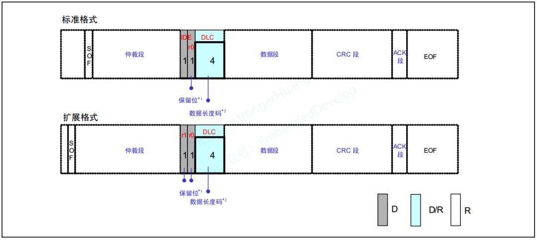
Indicates the segment that represents the number of data bytes and reserved bits.
Contains the data, which can send 0 to 8 bytes of data.
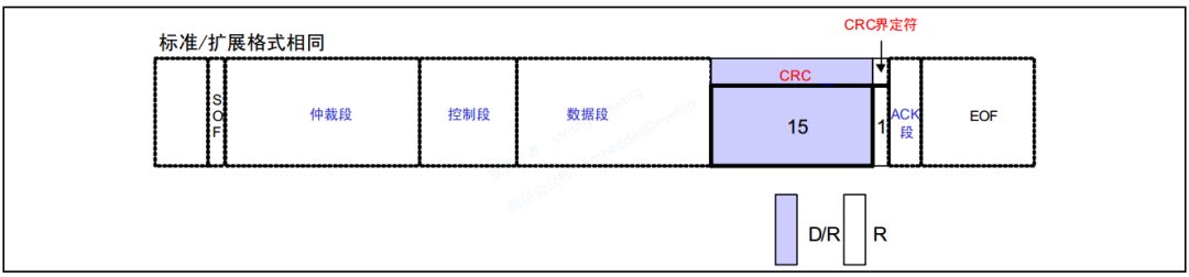
Checks for transmission errors in the frame.
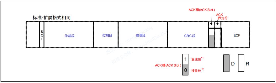
Indicates the segment that confirms normal reception.
Indicates the segment where the data frame ends.
To understand the meaning of the data frame, please carefully understand its definition: A frame used to send data from the sending unit to the receiving unit.
In general CAN bus communication, most communications on the bus are data frames. For instance, in the CANOpen protocol, the most used PDO (Process Data Object) communication is done through data frames.
Beginners can start by understanding the data frame, and then the rest will be easier to understand. Next, let’s discuss the details of the 7 segments of the data frame.
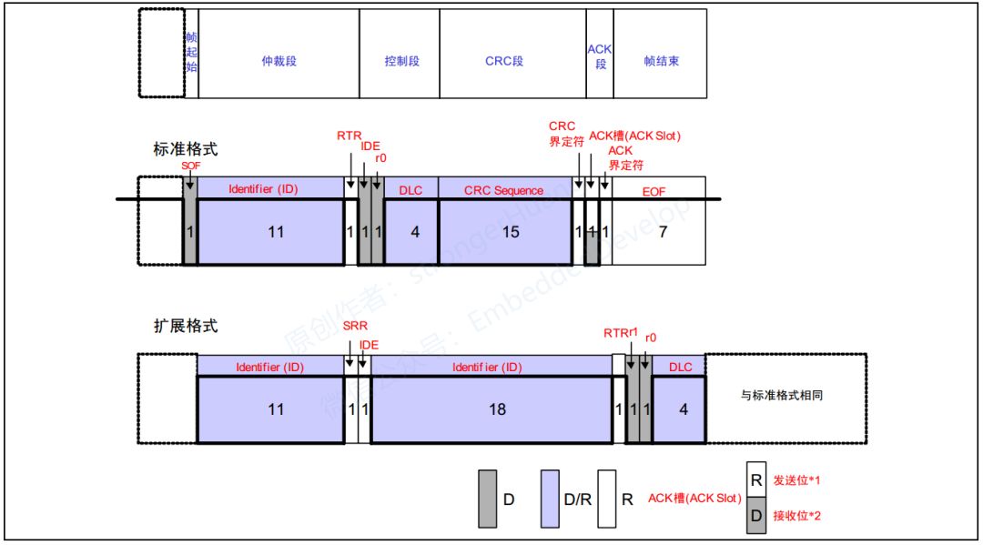
Standard and extended formats are the same. Indicates the segment where the frame starts, consisting of 1 dominant bit (as shown below):
For information about dominant and recessive levels, please refer to my previous article on differential signals.
There are dominant and recessive levels on the bus.
When performing logical AND on the bus, the logic value of the dominant level is ‘0’, and the recessive level is ‘1’.
The term ‘dominant’ implies ‘priority’; as long as one unit outputs a dominant level, it is considered dominant on the bus. Meanwhile, ‘recessive’ implies ‘inclusiveness’; only when all units output a recessive level is the bus recessive (the dominant level is stronger than the recessive level).
The standard and extended formats differ in composition here. The arbitration segment indicates the priority of the frame, and the extended format adds 18 bits of ID (as shown below):
RTR = 0 represents a data frame, RTR = 1 represents a remote frame.
The reason it is called an arbitration segment is that it determines which node on the bus has the priority to send based on the ID. The smaller the ID (0 represents dominant), the higher the priority.
The standard and extended formats differ in composition. The control segment consists of 6 bits (as shown below):
They all have 4 bits representing the Data Length Code (DLC), while the standard frame has an IDE (value of 0) bit and r0 reserved bit, and the extended frame has r0 and r1 reserved bits.
The reserved bits must all be sent with a dominant level. However, the receiver can receive any combination of dominant, recessive, and their combinations.
The standard and extended formats are the same. The data segment represents the content of the transmitted data, outputting from MSB (most significant bit), and can send 0 to 8 bytes of data, with the length determined by the previous control segment.
The standard and extended formats are the same. The CRC segment checks for transmission errors in the frame, consisting of 15 bits of CRC sequence and 1 bit of CRC delimiter (used for separation).
Compared to communication like 485, the CAN controller has already performed the CRC check, so your program does not need to calculate it again, saving processor resources.
The standard and extended formats are the same. The ACK segment is used to confirm whether the message was received correctly. It consists of the ACK slot (ACK Slot) and the ACK delimiter, which are 2 bits.
A.The sending unit sends 2 recessive bits in the ACK segment.
B.The unit that receives the correct message sends a dominant bit in the ACK slot (ACK Slot), notifying the sending unit that the reception was successful. This is called ‘sending ACK’ or ‘returning ACK’.
The standard and extended formats are the same. The frame end indicates the end of the frame, consisting of 7 recessive bits.
Compared to the data frame, the remote frame is used by the receiving unit to request the sending unit to send data. Therefore, the remote frame does not have a data segment. Thus, the remote frame consists of the following 6 segments:
Indicates the segment where the frame starts.
Indicates the segment that represents the priority of the frame. It can request the data frame with the same ID.
Indicates the segment that represents the number of data bytes and reserved bits.
Checks for transmission errors in the frame.
Indicates the segment that confirms normal reception.
Indicates the segment where the remote frame ends.
The 6 segments are basically the same as those in the data frame, so I will not explain them one by one. Let’s discuss the differences between remote frames and data frames:
-
The RTR bit of the remote frame is a recessive bit, and there is no data segment.
-
The data frame without a data segment can be distinguished from the remote frame by the RTR bit.
Question 1: If the remote frame has no data segment, how is the data length code represented?
The data length code of the remote frame is represented by the data length code of the requested data frame.
Question 2: What is the purpose of a data frame without a data segment?
For example, it can be used for periodic connection confirmations/responses between units, or when the arbitration segment itself carries substantial information.
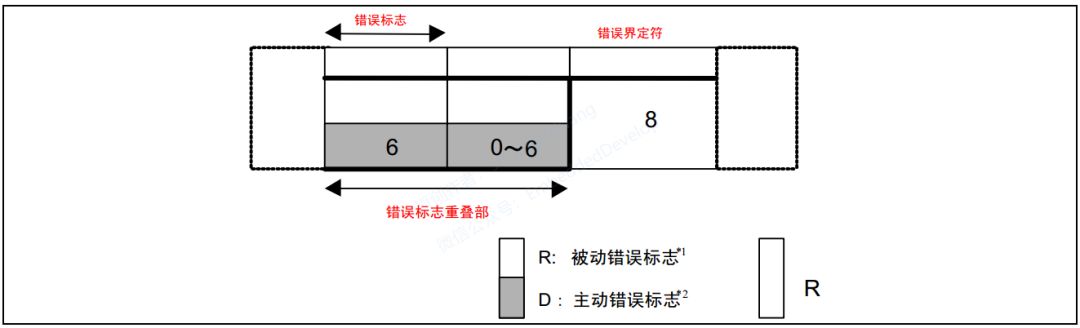
Used to notify errors when detecting errors during message reception and transmission. The error frame consists of an error flag and an error delimiter.
The error flag includes both active and passive error flags.
-
Active Error Flag: 6 dominant bits.
-
Passive Error Flag: 6 recessive bits.
The error delimiter consists of 8 recessive bits.
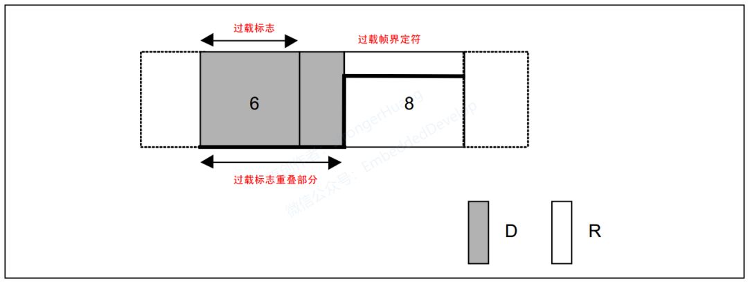
The overload frame is used by the receiving unit to notify that it is not yet ready to receive. The overload frame consists of an overload flag and an overload delimiter.
Consists of 6 dominant bits.
The composition of the overload flag is the same as that of the active error flag.
Consists of 8 recessive bits.
The composition of the overload delimiter is the same as that of the error delimiter.
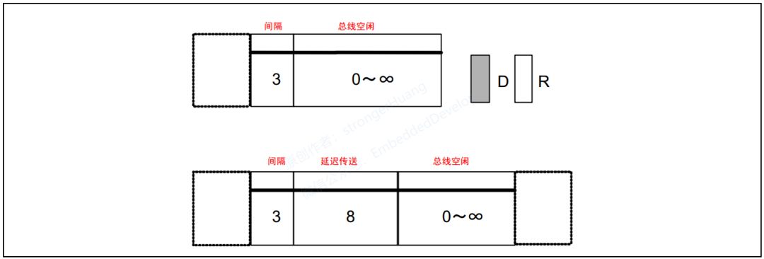
The frame interval is used to separate data frames and remote frames. Data frames and remote frames can be separated from any previous frame (data frame, remote frame, error frame, overload frame) by inserting a frame interval.
Frame intervals cannot be inserted before overload frames and error frames.
Recessive level, with no length limit (0 is also acceptable).
In this state, it can be considered that the bus is idle, and the units that need to send can start to access the bus.
(3) Delayed Transmission (temporary stop of sending)
Only included in the frame interval of a unit in passive error state that has just sent a message.
Author/Source: strongerHuang

Register for a Breadboard Community Account, new users receive free
Guanxin 32-bit 64-thread development board, first come first served!
↓ Scan to register for free ↓

Click to read the original text and register to receive