The serial port is a commonly used communication interface and is a necessary knowledge to master in embedded systems. However, I have found that many friends only know how to use the serial port to output or print some data, but do not know how to use the serial port for data transmission and communication.
What is a Communication Protocol?
The explanation from Baidu Baike:
A communication protocol refers to the rules and agreements that both parties must follow to complete communication or service. Multiple data communication systems connected through communication channels and devices in different geographical locations must have a common language to work together to achieve information exchange and resource sharing. What to communicate, how to communicate, and when to communicate must follow some mutually acceptable rules. This rule is the communication protocol.
-
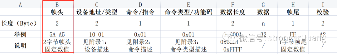
Frame Header -
Temperature Value -
Frame Tail
|
5A |
One-byte value |
3B |
Problems with Simple Communication Protocols
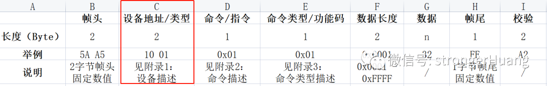
For example: How do you determine who to transmit to when multiple devices are connected on a single bus (like RS-485)? (No device information)
Additionally: In an interference environment, can you ensure the correctness of the transmitted data? (No verification information)
Furthermore: If I want to transmit multiple data of uncertain length, what should I do? (No length information).
Friends who have done custom communication will understand this series of problems.
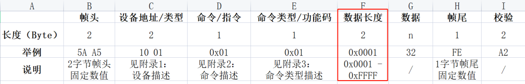
Common Contents of Communication Protocols
Serial-based communication protocols usually cannot be too complex due to serial communication speed, anti-interference capability, and other factors. Compared to TCP/IP communication protocols, it is a lightweight communication protocol.
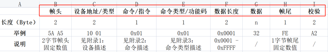

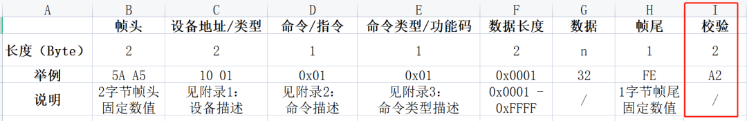
Additionally, some protocols may place the checksum second to last, with the frame tail at the last position.
Code Implementation of Communication Protocol
Of course, while implementing, you need to consider the actual situation of your project. For example, if there is a lot of communication data, you may need to use a message queue (FIFO). Additionally, if the protocol is complex, it is best to encapsulate structures, etc.
Below, I will share some code I have used before. It may not describe more details, but some ideas can be referenced.
1. Message Data Sending
(1) Directly Send Each Byte Through the Serial Port
This is something even beginners can understand. Here is an example from a previous DGUS serial screen:
#define DGUS_FRAME_HEAD1          0xA5                     //DGUS screen frame header 1#define DGUS_FRAME_HEAD2          0x5A                     //DGUS screen frame header 2
#define DGUS_CMD_W_REG            0x80                     //DGUS write register instruction#define DGUS_CMD_R_REG            0x81                     //DGUS read register instruction#define DGUS_CMD_W_DATA           0x82                     //DGUS write data instruction#define DGUS_CMD_R_DATA           0x83                     //DGUS read data instruction#define DGUS_CMD_W_CURVE          0x85                     //DGUS write curve instruction
/* DGUS register addresses */#define DGUS_REG_VERSION          0x00                     //DGUS version#define DGUS_REG_LED_NOW          0x01                     //LED backlight brightness#define DGUS_REG_BZ_TIME          0x02                     //Buzzer duration#define DGUS_REG_PIC_ID           0x03                     //Display page ID#define DGUS_REG_TP_FLAG          0x05                     //Touch coordinates update flag#define DGUS_REG_TP_STATUS        0x06                     //Coordinate status#define DGUS_REG_TP_POSITION      0x07                     //Coordinate position#define DGUS_REG_TPC_ENABLE       0x0B                     //Touch enable#define DGUS_REG_RTC_NOW          0x20                     //Current RTC
//Write one byte of data to the specified register of DGDS screenvoid DGUS_REG_WriteWord(uint8_t RegAddr, uint16_t Data){  DGUS_SendByte(DGUS_FRAME_HEAD1);  DGUS_SendByte(DGUS_FRAME_HEAD2);  DGUS_SendByte(0x04);
  DGUS_SendByte(DGUS_CMD_W_REG);                 //Instruction  DGUS_SendByte(RegAddr);                        //Address
  DGUS_SendByte((uint8_t)(Data>>8));             //Data  DGUS_SendByte((uint8_t)(Data&0xFF));}
//Write one byte of data to the specified address of DGDS screenvoid DGUS_DATA_WriteWord(uint16_t DataAddr, uint16_t Data){  DGUS_SendByte(DGUS_FRAME_HEAD1);  DGUS_SendByte(DGUS_FRAME_HEAD2);  DGUS_SendByte(0x05);
  DGUS_SendByte(DGUS_CMD_W_DATA);                //Instruction
  DGUS_SendByte((uint8_t)(DataAddr>>8));         //Address  DGUS_SendByte((uint8_t)(DataAddr&0xFF));
  DGUS_SendByte((uint8_t)(Data>>8));             //Data  DGUS_SendByte((uint8_t)(Data&0xFF));}
On the basis above, use a buffer to hold the message, then ‘package’ it into the message queue and send it out via the message queue method (FIFO).
static uint8_t  sDGUS_SendBuf[DGUS_PACKAGE_LEN];
//Write one byte of data to the specified register of DGDS screenvoid DGUS_REG_WriteWord(uint8_t RegAddr, uint16_t Data){  sDGUS_SendBuf[0] = DGUS_FRAME_HEAD1;           //Frame header  sDGUS_SendBuf[1] = DGUS_FRAME_HEAD2;  sDGUS_SendBuf[2] = 0x06;                       //Length  sDGUS_SendBuf[3] = DGUS_CMD_W_CTRL;            //Instruction  sDGUS_SendBuf[4] = RegAddr;                    //Address  sDGUS_SendBuf[5] = (uint8_t)(Data>>8);         //Data  sDGUS_SendBuf[6] = (uint8_t)(Data&0xFF);
  DGUS_CRC16(&sDGUS_SendBuf[3], sDGUS_SendBuf[2] - 2, &sDGUS_CRC_H, &sDGUS_CRC_L);  sDGUS_SendBuf[7] = sDGUS_CRC_H;                //Checksum  sDGUS_SendBuf[8] = sDGUS_CRC_L;
  DGUSSend_Packet_ToQueue(sDGUS_SendBuf, sDGUS_SendBuf[2] + 3);}
//Write one byte of data to the specified address of DGDS screenvoid DGUS_DATA_WriteWord(uint16_t DataAddr, uint16_t Data){  sDGUS_SendBuf[0] = DGUS_FRAME_HEAD1;           //Frame header  sDGUS_SendBuf[1] = DGUS_FRAME_HEAD2;  sDGUS_SendBuf[2] = 0x07;                       //Length  sDGUS_SendBuf[3] = DGUS_CMD_W_DATA;            //Instruction  sDGUS_SendBuf[4] = (uint8_t)(DataAddr>>8);     //Address  sDGUS_SendBuf[5] = (uint8_t)(DataAddr&0xFF);  sDGUS_SendBuf[6] = (uint8_t)(Data>>8);         //Data  sDGUS_SendBuf[7] = (uint8_t)(Data&0xFF);
  DGUS_CRC16(&sDGUS_SendBuf[3], sDGUS_SendBuf[2] - 2, &sDGUS_CRC_H, &sDGUS_CRC_L);  sDGUS_SendBuf[8] = sDGUS_CRC_H;                //Checksum  sDGUS_SendBuf[9] = sDGUS_CRC_L;
  DGUSSend_Packet_ToQueue(sDGUS_SendBuf, sDGUS_SendBuf[2] + 3);}
Structures are more convenient for referencing and managing than arrays; therefore, using structures is a higher-level and more practical method compared to arrays. (Of course, if there are many members, using temporary variables can lead to excessive stack usage.)
For example:
typedef struct{ uint8_t Head1; //Frame header 1 uint8_t Head2; //Frame header 2 uint8_t Len; //Length uint8_t Cmd; //Command uint8_t Data[DGUS_DATA_LEN]; //Data uint16_t CRC16; //CRC Checksum}DGUS_PACKAGE_TypeDef;
(4) More Other Methods
void DGUS_ISRHandler(uint8_t Data){  static uint8_t sDgus_RxNum = 0;                //Count  static uint8_t sDgus_RxBuf[DGUS_PACKAGE_LEN];  static portBASE_TYPE xHigherPriorityTaskWoken = pdFALSE;
  sDgus_RxBuf[gDGUS_RxCnt] = Data;  gDGUS_RxCnt++;
  /* Check Frame Header */  if(sDgus_RxBuf[0] != DGUS_FRAME_HEAD1)       //Received Frame Header  {    gDGUS_RxCnt = 0;    return;  }  if((2 == gDGUS_RxCnt) && (sDgus_RxBuf[1] != DGUS_FRAME_HEAD2))  {    gDGUS_RxCnt = 0;    return;  }
  /* Determine Frame Data Length */  if(gDGUS_RxCnt == 3)  {    sDgus_RxNum = sDgus_RxBuf[2] + 3;  }
  /* Received Complete Frame Data */  if((6 <= gDGUS_RxCnt) && (sDgus_RxNum <= gDGUS_RxCnt))  {    gDGUS_RxCnt = 0;
    if(xDGUSRcvQueue != NULL)                    //Parsing successful, add to queue    {      xQueueSendFromISR(xDGUSRcvQueue, &sDgus_RxBuf[0], &xHigherPriorityTaskWoken);      portEND_SWITCHING_ISR(xHigherPriorityTaskWoken);    }  }}
Receiving data may result in half-received data, and if the interrupt is interrupted for some reason, timeout detection is also very necessary.
For example: Use an extra MCU timer to handle a timeout count. When receiving data, start timing; if no next data is received within 1ms, discard this packet (the previously received).
static void DGUS_TimingAndUpdate(uint16_t Nms){  sDGUSTiming_Nms_Num = Nms;  TIM_SetCounter(DGUS_TIM, 0);                   //Set count value to 0  TIM_Cmd(DGUS_TIM, ENABLE);                     //Start timer}
void DGUS_COM_IRQHandler(void){  if((DGUS_COM->SR & USART_FLAG_RXNE) == USART_FLAG_RXNE)  {    DGUS_TimingAndUpdate(5);                     //Update timing (prevent timeout)    DGUS_ISRHandler((uint8_t)USART_ReceiveData(DGUS_COM));  }}
Final Words
Custom communication protocols based on serial ports vary greatly, depending on factors such as MCU processing capability, number of devices, communication content, etc.
Some may only require a very simple communication protocol to meet the requirements, while others may need a more complex protocol to satisfy.
Finally, two points to emphasize:
First, the examples above are not complete codes (some details are not described), mainly to provide everyone with learning about this programming idea or implementation method.
Second, a good communication protocol code must have certain fault tolerance handling, such as: send completion detection, receive timeout detection, data error detection, etc. Therefore, the above code is not complete.

END
→Follow to Avoid Getting Lost←