If you want to learn more related knowledge, please follow us for more knowledge sharing.
1. What is UART
UART (Universal Asynchronous Receiver/Transmitter) is a type of asynchronous serial communication protocol that transmits each character of data one bit at a time. It is the most frequently used data bus in application development.
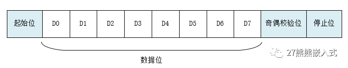
The characteristics of UART serial communication are that data is transmitted one bit at a time, and only two transmission lines are required for bidirectional communication; one line sends data while the other line receives data. UART serial communication has several important parameters, including baud rate, start bit, data bits, stop bit, and parity bit. For two ports using UART serial communication, these parameters must match; otherwise, communication cannot be completed successfully. The data format transmitted over UART is shown in the figure below:
-
Start Bit: Indicates the beginning of data transmission, with a logic level of “0”.
-
Data Bits: Possible values are 5, 6, 7, 8, or 9, indicating the number of bits being transmitted. Generally, the value is 8, as an ASCII character is 8 bits.
-
Parity Bit: Used by the receiver to check the received data. The number of bits with parity “1” can be even (even parity) or odd (odd parity), to verify the correctness of data transmission; this bit can also be omitted during use.
-
Stop Bit: Indicates the end of a data frame. The logic level is “1”.
-
Baud Rate: The rate of serial communication, expressed as the number of valid bits (bit) transmitted per unit time, with units of bits per second (bps). Common baud rates include 4800, 9600, 14400, 38400, and 115200, with higher values indicating faster data transmission. A baud rate of 115200 means 115200 bits of data are transmitted per second.
2. Connection Method
-
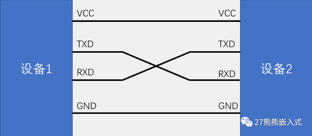
Simple bidirectional serial communication requires two communication lines (TXD for transmission and RXD for reception).
-
TXD and RXD should be cross-connected.
-
For unidirectional data transmission, one communication line is sufficient.
-
If the logic levels are inconsistent, a level-shifting chip is needed.
3. Communication Process
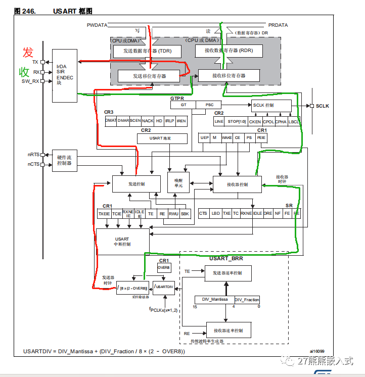
The red indicates transmission, while green indicates reception. The core part is to set the baud rate, which will be presented in the subsequent code, so it will not be introduced here.
4. Registers
Below is an example of the USART register for STM32F4.
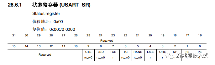
4.1 Status Register
As the name suggests, the status register stores the status information of the UART module.
-
TXE (Transmit Data Register Empty): Indicates whether the transmit data register is empty and if new data can be sent.
-
TC (Transmission Complete): Indicates whether the current data transmission is complete.
-
RXNE (Receive Data Register Not Empty): Indicates whether there is new data available to be read from the receive data register.
-
IDLE (Idle Line Detected): Indicates whether an idle line state has been detected, usually used to detect the end of a data frame.
-
ORE (Overrun Error): Indicates whether an overrun error has occurred, usually due to the receive data register not being read in time.
-
NE (Noise Error): Indicates whether a noise error has occurred, usually due to noise interference.
-
FE (Framing Error): Indicates whether a framing error has occurred, usually due to an error in the format of the received data frame.
-
PE (Parity Error): Indicates whether a parity error has occurred, typically used for parity bit checks in asynchronous serial communication.
These status bits can be used to monitor the operation of the USART module, detect errors, and control data transmission. The USART_SR register can be read as needed to obtain information about the communication status and take appropriate actions based on this information.Note that the exact layout of the USART_SR register and the names of the status bits may vary by chip model and manufacturer, so refer to the specific chip’s data sheet for detailed information.
4.2 Data Register
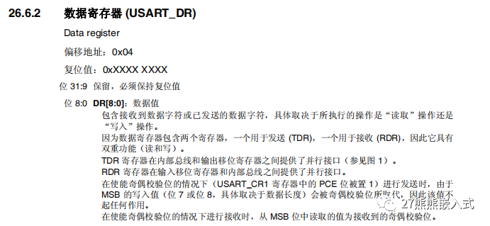
This is determined by the operation mode of the USART module (transmission or reception) and the configuration in the USART_CR1 register.
Specifically, the USART_DR register has dual functions, including:
-
Transmit Data (TDR): When the USART module is in transmission mode, you can load the data to be sent into the TDR register. This data will provide a parallel interface between the internal bus and the output shift register, ultimately transmitted via the serial communication line. If parity bit is enabled (the PCE bit in the USART_CR1 register is set to 1), the value of the MSB (Most Significant Bit, usually bit 7 or bit 8, depending on data length) in the TDR register will be replaced by the parity bit, so the value of the MSB may not take effect during transmission.
-
Receive Data (RDR): When the USART module is in reception mode, the received data character will be stored in the RDR register. You can read the RDR register to obtain the received data. In the case of enabled parity bit, the value read from the MSB of the RDR register usually represents the received parity bit.
This dual functionality allows the USART_DR register to flexibly handle data transmission and reception in serial communication, adapting automatically based on the operation mode and configuration. The configuration of the parity bit affects the interpretation of the data bits, so these factors should be considered when configuring the USART.
4.3 Baud Rate Register
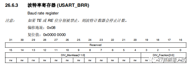
The USART_BRR register is used to set the baud rate for USART communication, which is the unit of data transmission rate, usually expressed in bits per second (bps).
The main function of the USART_BRR register is to determine the duration of each bit time (bit interval), thus controlling the rate of communication. Baud rate is a very important parameter in serial communication as it ensures data synchronization between sending and receiving devices.
The USART_BRR register typically contains two parts:
-
Integer Divider (DIV_Mantissa): This part is used to set the integer part of the baud rate. The value of the integer divider is an integer, usually represented as DIV_Mantissa, which determines the integer part of the baud rate. This value affects the duration of each bit time.
-
Fractional Divider (DIV_Fraction): This part is used to set the fractional part of the baud rate. The value of the fractional divider is a fraction, usually represented as DIV_Fraction, which determines the fractional part of the baud rate, allowing for finer adjustments.
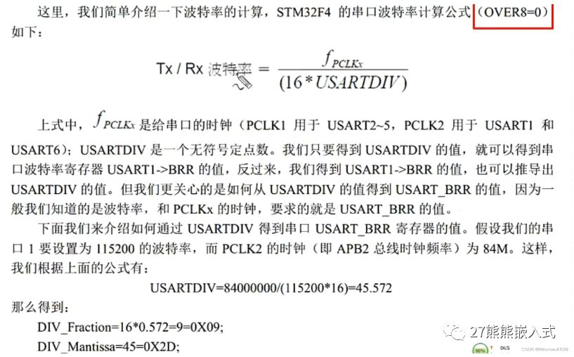
The baud rate is typically calculated as follows:
Baud Rate = Clock Frequency / (16 * (DIV_Mantissa + DIV_Fraction / 16))
4.4 Control Register 1
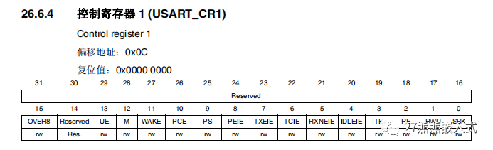
The USART_CR1 register is used to configure and control various parameters and functions of the USART module. This register allows you to define the operating mode, data format, parity method, and other communication parameters of the USART.
The USART_CR1 register usually includes multiple bits (or flags), each representing a specific configuration option or function of the USART module. Here are some common USART_CR1 register bits, although the exact bits and functionalities may vary by microcontroller model and manufacturer:
-
UE (USART Enable): This bit is used to enable or disable the USART module. Other parameters must be configured before enabling. When UE is set to 1, the USART module starts operating.
-
M (Word Length): This bit is used to select the length of the data frame, typically 8 or 9 bits.
-
PCE (Parity Control Enable): This bit is used to enable or disable the generation and checking of the parity bit.
-
PS (Parity Selection): If parity is enabled, this bit is used to select either odd or even parity.
-
TE (Transmitter Enable): This bit is used to enable or disable the transmitter.
-
RE (Receiver Enable): This bit is used to enable or disable the receiver.
-
IDLEIE (Idle Interrupt Enable): This bit is used to enable idle line detection interrupts.
-
RXNEIE (RX Not Empty Interrupt Enable): This bit is used to enable interrupts for the receive data register not being empty.
-
TCIE (Transmission Complete Interrupt Enable): This bit is used to enable transmission complete interrupts.
-
TXEIE (TX Empty Interrupt Enable): This bit is used to enable interrupts for the transmit data register being empty.
-
USART_OVER8: This bit is used to control the mode of operation of the USART’s baud rate modulator, typically either 8 or 16 bits.
-
WAKE (Wakeup Method): This bit is used to configure the wakeup method to wake the USART after it enters low power mode.
-
OVER8 (Oversampling Mode): This bit is used to configure the oversampling mode for high baud rates.
These bits allow customization of the behavior of the USART module to meet communication needs.
4.5 Control Register 2
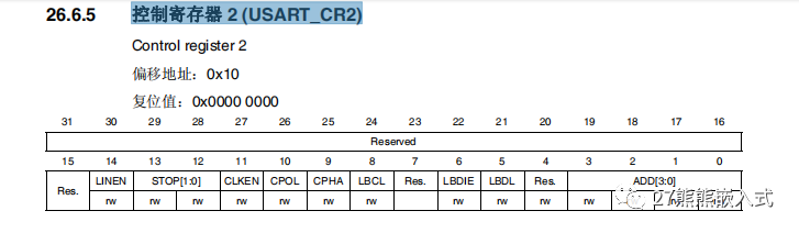
The USART_CR2 register is used to configure and control additional functions and parameters of the USART module, such as the number of stop bits and the direction of data transmission.
Here are some common USART_CR2 register bits, although the exact bits and functionalities may vary by microcontroller model and manufacturer:
-
STOP (Stop Bits): This bit is used to configure the number of stop bits. Typically, you can choose 1 or 2 stop bits.
-
STOP1/2 (Stop Bit 1/2): This bit is used to select the number of stop bits, typically used in conjunction with the STOP bit. When set to 1, it indicates the use of 1 stop bit; when set to 0, it indicates the use of 2 stop bits.
-
CLKEN (Clock Enable): This bit is used to enable the clock output of the USART, typically used in synchronous mode.
-
CPOL (Clock Polarity): In synchronous mode, this bit is used to configure the clock polarity, typically either high (1) or low (0).
-
CPHA (Clock Phase): In synchronous mode, this bit is used to configure the clock phase, usually either the first edge (1) or the second edge (0).
-
LBCL (Last Bit Clock Pulse): This bit is used to select whether to send or receive data on the last clock pulse of the last data bit. Typically, if set to 1, data will be sent/received on the last clock pulse.
-
LBDIE (Line Break Detection Interrupt Enable): This bit is used to enable line break detection interrupts.
-
LBDL (Line Break Detection Length): This bit is used to configure the data bit length for line break detection.
-
ADD[3:0] (Address of the USART node): This bit is used to configure the address of the USART node, typically used in multi-node communication.
The USART_CR2 register allows for more specific configuration of the USART’s operation, including the number of stop bits, clock settings, and multi-node communication.
4.6 Control Register 3
The USART_CR3 register is used to configure and control additional functions and parameters of the USART module, such as flow control, error detection, and DMA (Direct Memory Access).
Here are some common USART_CR3 register bits, although the exact bits and functionalities may vary by microcontroller model and manufacturer:
-
EIE (Error Interrupt Enable): This bit is used to enable error interrupts, such as noise errors and framing errors.
-
IREN (IrDA mode Enable): This bit is used to enable IrDA (Infrared Data Association) mode, typically for infrared communication.
-
IRLP (IrDA Low-Power): In IrDA mode, this bit is used to configure low-power mode.
-
HDSEL (Half-Duplex Selection): This bit is used to select half-duplex communication mode.
-
NACK (Smartcard NACK Enable): This bit is used to enable smart card NACK (No Acknowledge) functionality.
-
SCEN (Smartcard Mode Enable): This bit is used to enable smart card mode.
-
DMAR (DMA Enable Receiver): This bit is used to enable DMA functionality for receiving data.
-
DMAT (DMA Enable Transmitter): This bit is used to enable DMA functionality for transmitting data.
-
RTSE (RTS Enable): This bit is used to enable RTS (Request to Send) flow control.
-
CTSE (CTS Enable): This bit is used to enable CTS (Clear to Send) flow control.
-
CTSIE (CTS Interrupt Enable): This bit is used to enable CTS interrupts.
-
ONEBIT (One Sample Bit Method Enable): This bit is used to enable the one sample bit method.
The USART_CR3 register allows for configuring additional functions and parameters of the USART module to meet specific communication needs. The availability of functions and the exact bit fields may vary by different microcontrollers and USART modules, so refer to the specific chip’s data sheet for detailed information.
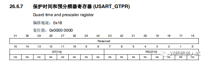
4.7 Guard Time and Prescaler Register

This register is mainly used to configure communication rate control parameters for the USART module, including baud rate prescaling and guard time.
Here are the general functions of the USART_GTPR register:
-
PSC (Prescaler Value): This is the USART baud rate prescaler used to divide the main system clock to achieve the desired baud rate. Typically, the value of PSC can be calculated based on the baud rate to ensure that the communication clock matches the expected baud rate.
-
GT (Guard Time Value): This is the USART guard time value used to ensure the stability and synchronization of the communication clock. The guard time is the idle time between sending and receiving, usually measured in clock cycles.
5. Programming Process
-
Enable the serial clock and GPIO clock.
-
Set the pin multiplexer mapping: call the GPIO_PinAFConfig function.
-
GPIO initialization settings: set the mode to alternate function.
-
Initialize serial parameters: set baud rate, word length, parity, etc.
-
Enable interrupts and initialize NVIC to enable interrupts (this step is only needed if interrupts are to be enabled).
-
Enable the serial port.
-
Write the interrupt handler function: the function name format is USARTxIRQHandler (x corresponds to the serial port number).
USART Library Function Interface
/* Function used to set the USART configuration to the default reset state ***/ void USART_DeInit(USART_TypeDef* USARTx); /* Initialization and Configuration functions *********************************/void USART_Init(USART_TypeDef* USARTx, USART_InitTypeDef* USART_InitStruct);void USART_StructInit(USART_InitTypeDef* USART_InitStruct);void USART_ClockInit(USART_TypeDef* USARTx, USART_ClockInitTypeDef* USART_ClockInitStruct);void USART_ClockStructInit(USART_ClockInitTypeDef* USART_ClockInitStruct);void USART_Cmd(USART_TypeDef* USARTx, FunctionalState NewState);void USART_SetPrescaler(USART_TypeDef* USARTx, uint8_t USART_Prescaler);void USART_OverSampling8Cmd(USART_TypeDef* USARTx, FunctionalState NewState); /* Data transfers functions ***************************************************/ void USART_SendData(USART_TypeDef* USARTx, uint16_t Data);uint16_t USART_ReceiveData(USART_TypeDef* USARTx); /* Multi-Processor Communication functions ************************************/void USART_SetAddress(USART_TypeDef* USARTx, uint8_t USART_Address);void USART_WakeUpConfig(USART_TypeDef* USARTx, uint16_t USART_WakeUp);void USART_ReceiverWakeUpCmd(USART_TypeDef* USARTx, FunctionalState NewState); /* LIN mode functions *********************************************************/void USART_LINBreakDetectLengthConfig(USART_TypeDef* USARTx, uint16_t USART_LINBreakDetectLength);void USART_LINCmd(USART_TypeDef* USARTx, FunctionalState NewState);void USART_SendBreak(USART_TypeDef* USARTx); /* Half-duplex mode function **************************************************/void USART_HalfDuplexCmd(USART_TypeDef* USARTx, FunctionalState NewState); /* Smartcard mode functions ***************************************************/void USART_SmartCardCmd(USART_TypeDef* USARTx, FunctionalState NewState);void USART_SmartCardNACKCmd(USART_TypeDef* USARTx, FunctionalState NewState);void USART_SetGuardTime(USART_TypeDef* USARTx, uint8_t USART_GuardTime); /* IrDA mode functions ********************************************************/void USART_IrDAConfig(USART_TypeDef* USARTx, uint16_t USART_IrDAMode);void USART_IrDACmd(USART_TypeDef* USARTx, FunctionalState NewState); /* DMA transfers management functions *****************************************/void USART_DMACmd(USART_TypeDef* USARTx, uint16_t USART_DMAReq, FunctionalState NewState); /* Interrupts and flags management functions **********************************/void USART_ITConfig(USART_TypeDef* USARTx, uint16_t USART_IT, FunctionalState NewState);FlagStatus USART_GetFlagStatus(USART_TypeDef* USARTx, uint16_t USART_FLAG);void USART_ClearFlag(USART_TypeDef* USARTx, uint16_t USART_FLAG);ITStatus USART_GetITStatus(USART_TypeDef* USARTx, uint16_t USART_IT);void USART_ClearITPendingBit(USART_TypeDef* USARTx, uint16_t USART_IT);Here I provide a simple example code; of course, there are other ways, and I will not elaborate further. I believe everyone understands, and please point out any errors for mutual improvement.
//USART1 initializationvoid Init_USART1(uint32_t baud){ //GPIO structure GPIO_InitTypeDef GPIO_InitStructure; //Interrupt vector structure, provides interrupt controller NVIC_InitTypeDef NVIC_InitSructure; //Serial structure USART_InitTypeDef USART_InitSructure; //1. Enable the hardware clock for USART1 RCC_AHB1PeriphClockCmd(RCC_AHB1Periph_GPIOA, ENABLE); RCC_APB2PeriphClockCmd(RCC_APB2Periph_USART1, ENABLE); //2. Configure GPIO_PinAFConfig() GPIO_PinAFConfig(GPIOA, GPIO_PinSource9, GPIO_AF_USART1); GPIO_PinAFConfig(GPIOA, GPIO_PinSource10, GPIO_AF_USART1); GPIO_InitStructure.GPIO_Pin = GPIO_Pin_9; //Pin 9 GPIO_InitStructure.GPIO_Mode = GPIO_Mode_AF; //Alternate function mode GPIO_InitStructure.GPIO_OType = GPIO_OType_PP; //Push-pull mode, increases driving capability; GPIO_InitStructure.GPIO_Speed = GPIO_High_Speed; //Operating speed at 100MHz, higher performance, greater consumption GPIO_InitStructure.GPIO_PuPd = GPIO_PuPd_NOPULL; //No pull-up or pull-down needed GPIO_Init(GPIOA, &GPIO_InitStructure); //Initialization GPIO_InitStructure.GPIO_Pin = GPIO_Pin_10; //Pin 10 GPIO_Init(GPIOA, &GPIO_InitStructure); //Initialization //3. Configure USART_Init() USART_InitSructure.USART_BaudRate = baud; //Baud rate USART_InitSructure.USART_HardwareFlowControl = USART_HardwareFlowControl_None; //No hardware flow control USART_InitSructure.USART_Mode = USART_Mode_Rx | USART_Mode_Tx; //Data transmission and reception function USART_InitSructure.USART_Parity = USART_Parity_No ; //Parity bit USART_InitSructure.USART_StopBits = USART_StopBits_1; //Stop bit USART_InitSructure.USART_WordLength = USART_WordLength_8b; //Data bits USART_Init(USART1, &USART_InitSructure); //4. NVIC NVIC_InitSructure.NVIC_IRQChannel = USART1_IRQn; NVIC_InitSructure.NVIC_IRQChannelPreemptionPriority = 0x01; //Preemption priority NVIC_InitSructure.NVIC_IRQChannelSubPriority = 0x01; //Response priority NVIC_InitSructure.NVIC_IRQChannelCmd = ENABLE; NVIC_Init(&NVIC_InitSructure); //5. USART_Cmd(), enable USART1 USART_Cmd(USART1, ENABLE); //6. USART_ITConfig(), enable data reception USART_ITConfig(USART1, USART_IT_RXNE, ENABLE); } //Data reception buffer uint8_t date_buf[DATE_SIZE_MAX]; uint16_t date_num; uint8_t receive_flg; //Serial interrupt service function void USART1_IRQHandler(void){ if(USART_GetFlagStatus(USART1, USART_FLAG_RXNE))//If there is data { if(receive_flg ) { date_buf[date_num++] = USART_ReceiveData(USART1); //Check if the buffer is full or ends with \r\n if(receive_num==DATE_SIZE_MAX||(date_buf[date_num-1]=='\n'&&date_buf[date_num-2]=='\r')) { receive_flg = 0; } } USART_ClearFlag(USART1, USART_FLAG_RXNE); }} //Also can use redefined fput function to implement printf serial printing //Send uint8_t data uint8_t USART1_send(uint8_t ch){ //Wait for USART1 transmission complete flag (USART_FLAG_TC) to be set, ensuring USART1 send register is empty and previous data transmission is completed while(USART_GetFlagStatus(USART1,USART_FLAG_TC)==RESET); USART_SendData(USART1,ch); //Wait for USART1 send data register empty flag (USART_FLAG_TXE) to be set, ensuring data has been transmitted to USART1 data register while(USART_GetFlagStatus(USART1,USART_FLAG_TXE)==RESET); return ch;} //Send string uint8_t USART1_sendstr(uint8_t *str){ uint8_t i = 0; while (*str) { USART1_send(*str); i++; str++; } return i;} int main(){ Init_USART1(115200); while(1) { if(receive_flg ==0) { USART1_sendstr(date_buf); receive_flg=1; date_num=0; str_clear(date_buf); } delay_ms(100); }}-
Recommended Previous Content
-
How much do you know about interrupts?
-
What are push-pull and open-drain?
-
STM32’s clock
-
The Past and Present of SPI Protocol
That concludes this sharing session. Thank you all for your patience in watching; following us can improve learning efficiency.
Thank you all for your support! Following us can improve learning efficiency!See you next time!

Follow our public account and reply with “motor” to receive FOC motor control materials.