Click the Blue Text
1. Introduction
1. Concept
The IIC protocol (I²C, or Inter-Integrated Circuit) is a widely used low-speed serial half-duplex communication protocol for communication between integrated circuits, allowing only unidirectional communication at any one time. It was invented by Philips in the 1980s and is widely used for data transmission between microcontrollers, sensors, displays, and other devices.
2. Features
-
Two-wire structure: I²C uses two signal lines for communication, namely SDA (data line) and SCL (clock line). -
Multi-master/slave structure: I²C supports multiple master and slave devices, meaning multiple master devices can control the bus and communicate with multiple slave devices. -
Addressing mechanism: Each device connected to the I²C bus has a unique address, allowing the master device to select the slave device to communicate with. -
Data transmission rates: I²C has standard mode (100 kbps), fast mode (400 kbps), high-speed mode (3.4 Mbps), and ultra-fast mode (5 Mbps). -
Synchronous communication: The SCL clock line is used to synchronize data transmission, ensuring data can be correctly read during transmission.
Disadvantages:
4. Applications
2. Working Principle
1. Physical Layer
The common connection method between I2C devices is shown in Figure 1.
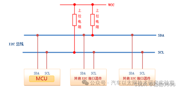
Figure 1
To distinguish devices, each device connected to the bus must have a unique address (the address can be determined by physical grounding or pulling high, as can be found in the I2C device’s datasheet). The communication between master and slave devices is determined by this address. In typical applications, the module with the I2C bus interface connected to the CPU is considered the master device, while the other devices mounted on the bus are considered slave devices. The master can access different devices through this address. When multiple masters use the bus simultaneously, arbitration is used to determine which device occupies the bus to prevent data conflicts.
Arbitration on the IIC Bus:
I2C allows multiple master devices and multiple slave devices. If two or more master devices simultaneously send a start signal to the bus and begin transmitting data, a conflict occurs. To resolve this conflict, arbitration is necessary, which is the arbitration on the I2C bus.
Arbitration on the I2C bus consists of two parts: synchronization on the SCL line and arbitration on the SDA line. Simply put, it follows the principle of “low level first”, meaning whoever sends a low level first takes control of the bus.
For convenience, we typically classify IIC devices into master and slave devices, where the device controlling the clock line (i.e., controlling the high and low levels of SCL) is the master device.
2. Protocol Layer
(1) Signal Generation and Introduction
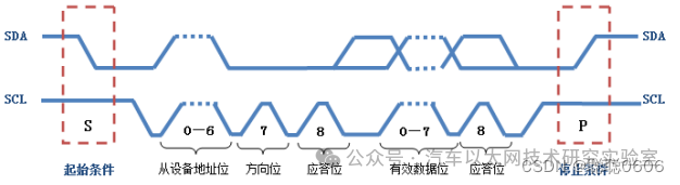
During data transmission on the I2C bus, there are three types of signals: start signal, stop signal, and acknowledgment signal.
The I2C protocol stipulates that data transmission on the bus must begin with a start signal and end with a stop signal. Start and stop signals are always generated by the master device, and all communication is initiated by the master device, which can issue a query command and then wait for communication from the slave device.
-
Start Signal:When SCL is high, SDA transitions from high to low, indicating the start of data transmission.
-
Stop Signal:When SCL is high, SDA transitions from low to high, indicating the end of data transmission.
-
Acknowledgment Signal:The IC receiving the data sends a specific low-level pulse to the sending IC after receiving 8 bits of data, indicating that the data has been received. After the CPU sends a signal to the controlled unit, it waits for the controlled unit to send an acknowledgment signal. Upon receiving the acknowledgment signal, the CPU decides whether to continue transmitting signals based on the actual situation. If no acknowledgment signal is received, it is judged that the controlled unit has failed.
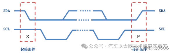
To distinguish between the start and stop signals, remember the phrase: “Whoever pulls low first, pulls high last”. This means that during the start condition, SDA is pulled low before SCL, and during the stop condition, SDA is pulled high after SCL.
After the start condition is generated, the bus is busy, exclusively occupied by the master and slave devices involved in this data transmission, and other I2C devices cannot access the bus; after the stop condition is generated, the master and slave devices involved in this data transmission release the bus, and the bus becomes idle again.
(2) Data Transmission
Data transmission occurs byte by byte. During each clock pulse generated by the master device on the SCL line, a data bit is transmitted on the SDA line. Once a byte is transmitted from high bit to low bit, the slave device pulls the SDA line low to send an acknowledgment bit back to the master device, indicating that the byte has been successfully transmitted. Of course, not all byte transmissions must have an acknowledgment bit; for example, when the slave device cannot receive more data sent by the master device, it will send a negative acknowledgment bit back. The data transmission process is illustrated in the figure.
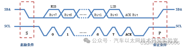
(3) Address Specification
As mentioned earlier, each device on the I2C bus corresponds to a unique address. The data transmission between master and slave devices is based on this address, meaning that the master device must specify the slave device’s address before transmitting valid data. The address specification process is similar to the data transmission process mentioned above, except that most slave devices have a 7-bit address, and the protocol stipulates that an additional least significant bit is added to indicate the direction of the data transmission: 0 indicates the master device is writing data to the slave device, and 1 indicates the master device is reading data from the slave device. The format for sending data to the specified device is shown in the figure: (each minimum data packet consists of 9 bits, 8 bits of content + 1 bit ACK; if it is address data, the 8 bits include 1 bit for direction).
3. Code Programming
Using Z20k118 as an example, this section demonstrates how to use I2C to transmit data, with the complete project available in the resources.
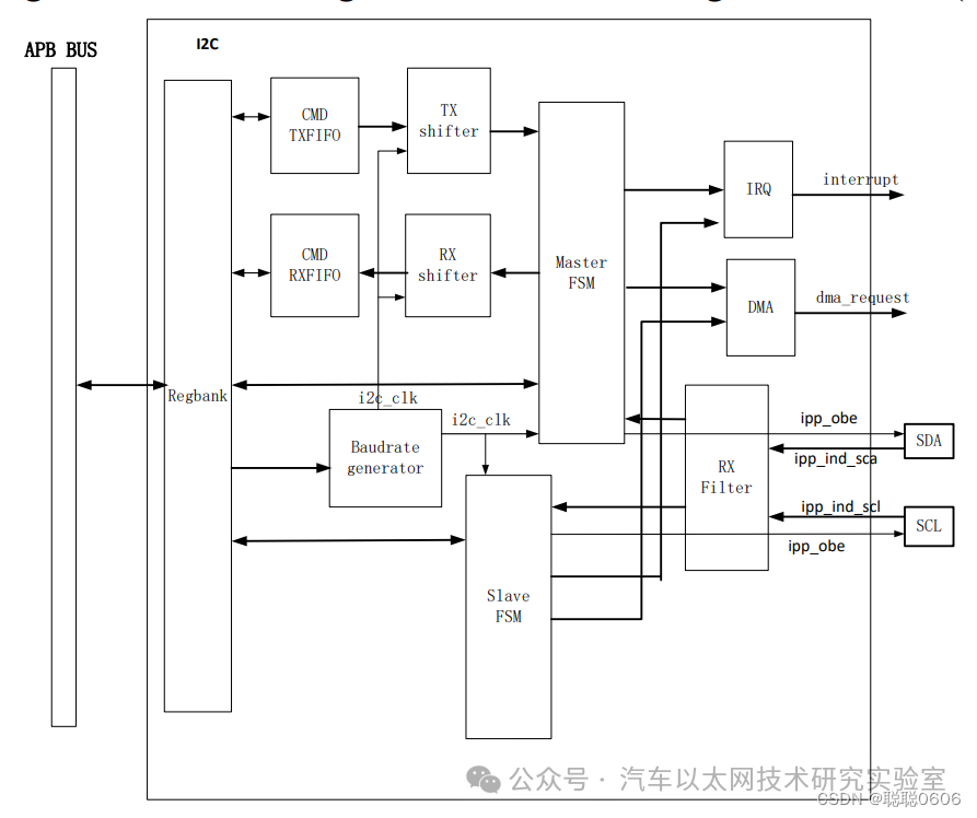
1. Hardware Block Diagram
2. Main Code
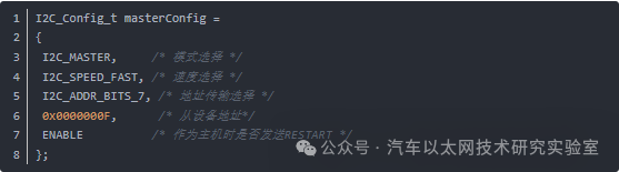
① I2C Structure Initialization
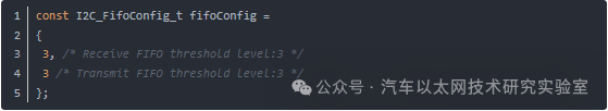
② Configure Receive and Transmit FIFO Depth
③ Define Data to be Sent

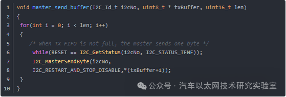
④ Define Host Sending Buffer Data
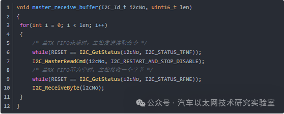
⑤ Host Receives Data from Slave
⑥ Initialization, Receive and Send Function Calls