
|
|
|
|
|
|
|
|
|
|
|
|
|
|
|
|
|
|
|
|
|
|
|
|
|
|
|
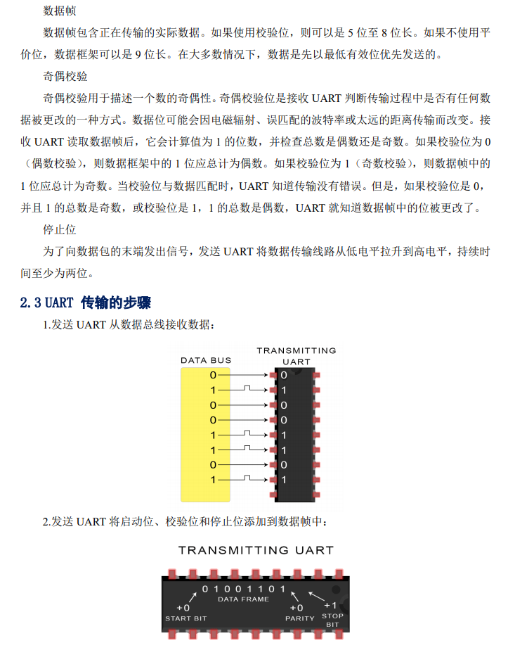
3.2 How It Works
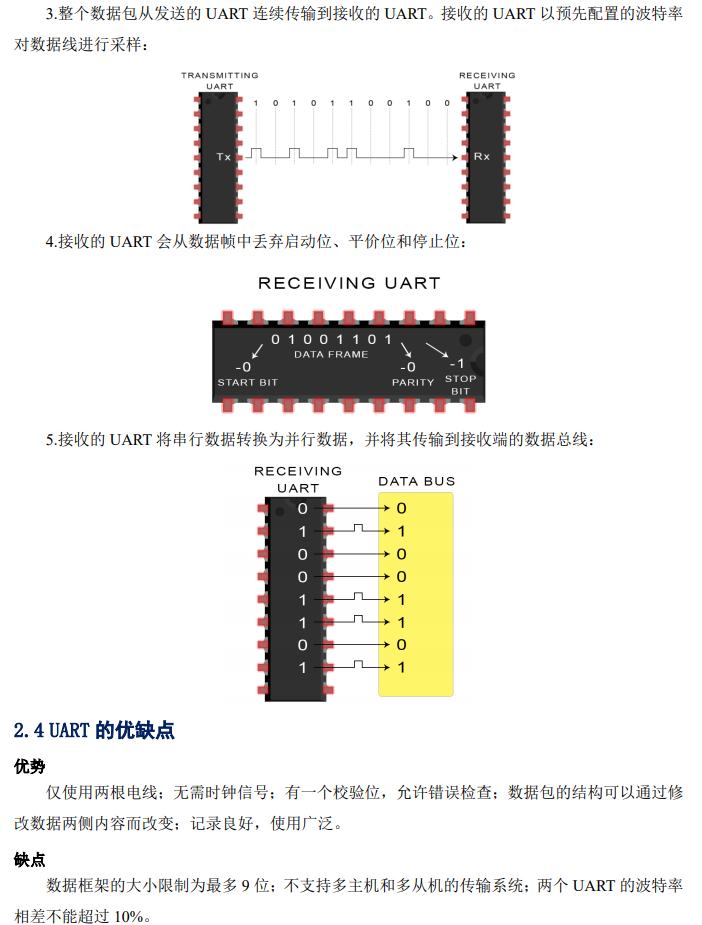
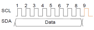
Data is transmitted in messages. The message is divided into data frames. Each message has an address frame containing the binary address of the slave, as well as one or more data frames containing the data being transmitted. The message also includes start and stop conditions between each data frame, read/write bits, and ACK/NACK bits:
-
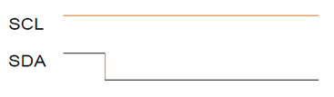
Start Condition:SDA line switches from high to low before SCL line switches from high to low.
-
Stop Condition:SDA line switches from low to high after SCL line switches from low to high.
-
Address Frame:Each slave has a unique 7-bit or 10-bit number that the master can use to identify the slave. If the master needs to send/receive data to/from the slave, it must first send the corresponding slave’s address, which will then match the address of the slave mounted on the bus.
-
Read/Write Bit:This is a single bit that specifies whether the master wants to send data to the slave (low) or request data from the slave (high).
-
ACK/NACK Bit:In a message, each frame is followed by one acknowledgment (ACK) / non-acknowledgment (NACK) bit. If an address frame or data frame is successfully received, an acknowledgment bit (ACK bit) will be returned from the receiving device to the sending device.
3.3 Addressing
Unlike SPI, which has a slave chip select line, I2C requires another way for the slave to know that data is being sent to it rather than another slave. It achieves this through addressing. The address frame is always the first frame after the start bit in a new message.
The master sends the address of the slave it wants to communicate with to every slave connected to it. Each slave then compares the address sent by the master with its own address. If the address matches, it will return a low voltage ACK bit to the master. If the address does not match, the slave does nothing, and the SDA line remains high.
3.4 Read/Write Bit
At the end of the address frame, there is a single bit that notifies the slave whether the master wants to write data to it or receive data from it. If the master wants to send data to the slave, the read/write bit is low; if the master requests data from the slave, this bit is high.
3.5 Data Frame
After the master detects the ACK bit sent by the slave, the first data frame is ready to be sent.
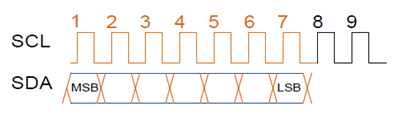
Data frames are always 8 bits long, and the most significant bit is sent first. Each data frame is immediately followed by an ACK/NACK bit to verify whether the frame was successfully received. Before sending the next data frame, the master or slave (depending on who is sending data) must receive the ACK bit.
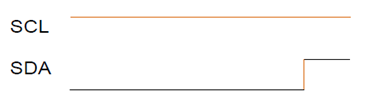
After all data frames have been sent, the master can send the stop condition to the slave to stop the transmission. The stop condition is when the voltage on the SDA line transitions from low to high after the SCL line transitions from low to high, while the SCL line remains high.
3.6 Steps of I2C Data Transmission
1. The master sends a start condition to each connected slave by switching the SDA line from high to low before the SCL line switches from high to low, triggering the start condition, as shown in the diagram below:
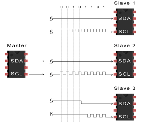
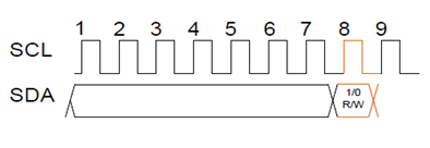
2. The master sends the 7-bit or 10-bit address of the slave it wants to communicate with, along with the read/write bit:
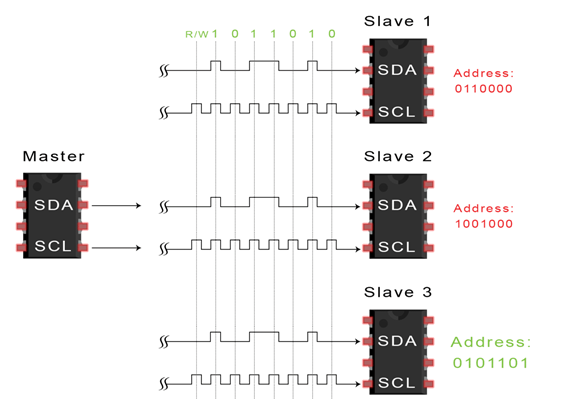
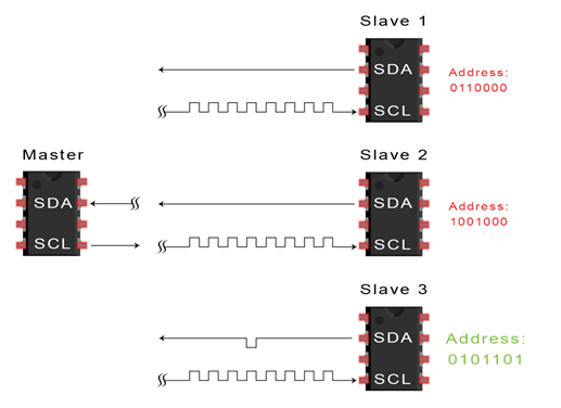
3. Each slave compares the address sent by the master with its own address. If the address matches, the slave responds with an ACK bit by pulling the SDA line low. If the master’s address does not match the slave’s own address, the slave leaves the SDA line high (through a pull-up resistor). The matching slave returns the ACK bit as shown in the diagram below:
4. The master sends or receives data frames:
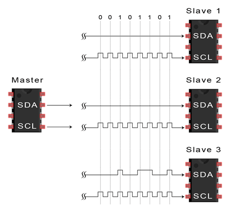
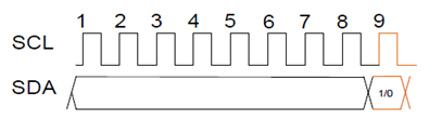
5. After transmitting each data frame, the receiving device returns another ACK bit to the sender to confirm successful reception of the frame:
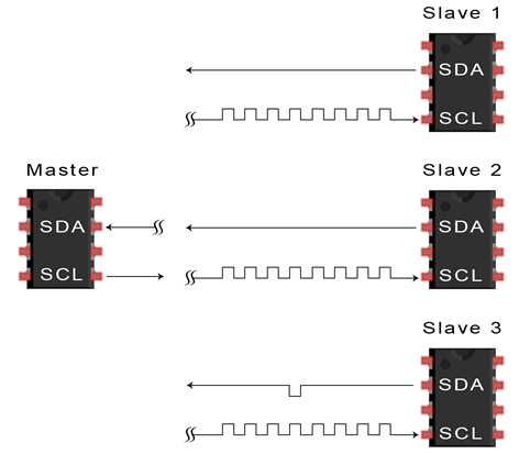
6. To stop data transmission, the master sends a stop condition to the slave by pulling the SCL line high before pulling the SDA line high, which generates a rising edge on the SDA line while SCL is high, as shown in the diagram below:
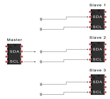
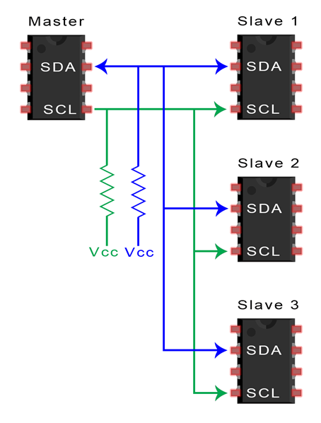
3.7 Single Master with Multiple Slaves
Due to addressing, a single master can control multiple slaves. Theoretically, using a 7-bit address provides 128 (2^7) unique addresses. Using a 10-bit address is not common but theoretically provides 1024 (2^10) unique addresses. To connect multiple slaves to a single master, connect them as shown below, and use a 4.7K Ohm pull-up resistor to connect the SDA and SCL lines to Vcc:
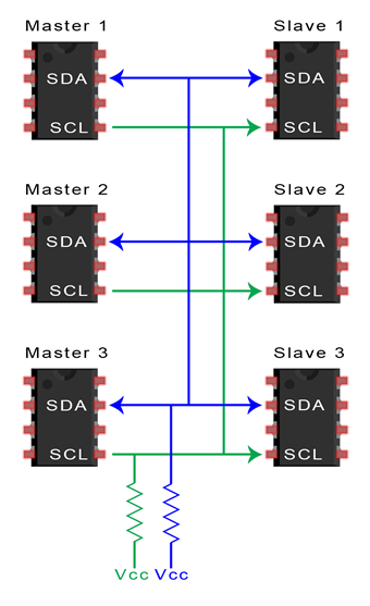
3.8 Multiple Masters with Multiple Slaves
Multiple masters can connect to a single slave or multiple slaves. In a multi-master system, problems arise when two masters attempt to send or receive data simultaneously via the SDA line. To resolve this issue, each master needs to check whether the SDA line is low or high before transmitting a message. If the SDA line is low, it means another master is controlling the bus, and that master should wait to send a message. If the SDA line is pulled high, it is safe to transmit the message.
To connect multiple masters to multiple slaves, connect them as shown below and use a 4.7K Ohm pull-up resistor to connect the SDA and SCL lines to Vcc:
3.9 Advantages and Disadvantages
Advantages:
-
Uses only two wires
-
Supports multiple masters and slaves
-
ACK/NACK bits confirm that each frame is successfully transmitted
-
Hardware is less complex than UART
-
Well-known and widely used protocol
Disadvantages:
-
Data transmission rate is lower than SPI
-
Data frame size is limited to 8 bits
-
Hardware required for implementation is more complex than SPI
3.10 Summary
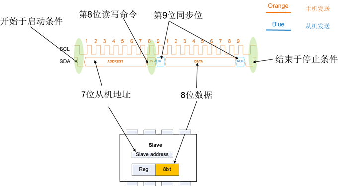
The bus consists of 9-bit blocks. Start Condition: When SCL is high, the SDA line transitions from high to low, serving as the start condition. All slaves on the bus must start paying attention:
The address bit is the 7-bit data that immediately follows the start condition, which the master wants to communicate with the slave at that address:
The read/write bit is the 8th bit immediately following the 7-bit address: this bit indicates whether the master wants to read from or write to the slave: 1 indicates read; 0 indicates write.
The synchronization bits between the master and slave: 0 indicates ACK; 1 indicates NACK. 0: I have it or data has been received. 1: I do not have it or data has not been received.
Data byte: The 8 bits following the address byte are the data bytes from the master or slave. As for who it comes from depends on the read/write bit. During the write cycle, the master sends data; during the read cycle, the slave sends data:
Stop Condition: When SCL is high, the SDA line transitions from low to high, generating a rising edge that serves as the stop condition. The master notifies the slave that the communication has ended.
The complete bus protocol timing is shown in the diagram below:
3.11 Notes
The arrows in the diagrams indicate the priority order of the timing transfer, and the arrows indicate the direction of data transfer or the timing that occurs first. In section 1.10, no arrows are marked, with the left side as the first occurring timing; do not confuse it with the previous diagrams.
Statement:This article was translated by gaoyang9992006 from the 21ic forum based on external sources and Philips-related technical documents, supplemented by personal understanding. For a high-definition PDF version, please click the “Read Original” link at the end of the article to view and download.

END
Author: gaoyang9992006
→ Follow for updates ←