With the advancement of technology, an increasing number of PLCs (Programmable Logic Controllers) are being applied in the automation control of machinery.Currently, many electricians tend to avoid dealing with them, lacking the knowledge to troubleshoot these types of faults.
In fact, we can think of PLC control as being quite similar to the traditional button control method; the only difference is the operator. One method collects data through various sensors, processes it, and outputs values set by the operator, while the other relies on human judgment to operate buttons.
Therefore, when searching for faults in PLC control circuits, we can divide the inspection into two parts: one is the fault in the peripheral control circuit of the PLC, and the other is the fault within the PLC controller itself.
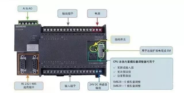
Before troubleshooting the PLC control circuit, we must understand what wires are connected to each input and output terminal of the PLC. This requires us to be able to read electrical schematics, which indicate the numbering of the PLC input and output terminals along with their corresponding electrical symbols and the names of the connected electrical components.
Before addressing the fault, we need to identify which part is malfunctioning. For example, there was a case where a newly acquired fully automatic labeling machine in a pharmaceutical factory kept triggering alarms. Upon inspection, I found that the values that could trigger the alarm on the touchscreen were normal. I could only refer to the electrical schematic and wiring diagram provided by the manufacturer, which indicated that the alarm was directly connected to the PLC’s N3 terminal and was directly controlled by the PLC, with the indicator light below the terminal lit. After checking several aspects and finding them normal, I could only suspect that there was an anomaly in the PLC’s internal program or a fault in the PLC output point. After removing the terminal wiring and measuring the resistance between that terminal and the common point, I found it to be very low, indicating it was damaged. The manufacturer provided a new PLC, and after installation, it returned to normal operation.
This troubleshooting approach is based on the occurrence of the alarm fault.
(1) First, check if it is caused by a soft fault, whether the related parameter settings are reasonable, and if the actual values exceed the set range.(2) Check if there are any damaged peripheral electrical components of the PLC.
(3) Check if there are any damaged components within the PLC itself or if the programming is disordered.
In summary, PLC faults can be categorized into peripheral and internal faults. We observe the indicator lights of each terminal on the PLC (generally, the failure rate of indicator lights is very low) to see if they are flashing or extinguished. If the indicator light is on, it usually indicates a fault in the peripheral. The inspection of peripheral components of the PLC is generally similar to our previous inspection methods, with the addition of sensor checks. For the touchscreen that matches the PLC, we only need to check if the data settings are reasonable. The internal inspection of the PLC should verify whether the terminal is functioning normally when output conditions are met or when there is an input signal.
In conclusion, most PLC control circuit faults occur in the peripherals.The above points are based on the repair experiences of those who have gone through similar issues; any shortcomings are welcome for critique and discussion for mutual improvement.