
Long press the QR code to recognize, follow, click “Skill Enhancement” to browse technical articles and download free materials.
The article is long, it is recommended to save it for later use, all images in the article can be clicked to enlarge for clarity!
 Guide
Guide
Different motor control methods, different components selected in the system, different combinations of components, and the selection of quantities lead to different PLC control methods. We need some cases to understand the ladder diagrams and statement tables of PLC in motor control systems.


Ladder Diagram and Statement Table of PLC in Continuous Control Circuit of Three-Phase AC Induction Motor
The continuous control circuit of the three-phase AC induction motor mainly adopts the control method of AC relays and contactors. This control method has disadvantages such as low reliability and difficulty in circuit maintenance, which will directly affect the production efficiency of enterprises. Therefore, many manufacturing enterprises adopt PLC control methods for control.
Figure 1 shows the schematic diagram of the continuous control circuit of the three-phase AC induction motor. This control circuit uses Mitsubishi FX2N series PLC, and the I/O distribution table controlled by PLC in the circuit is shown in Table 1.
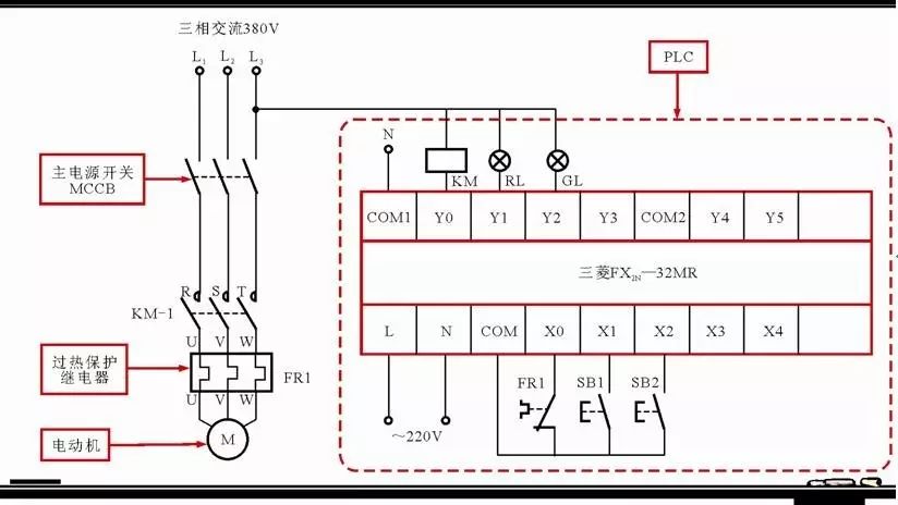 Figure 1 Schematic Diagram of Continuous Control Circuit of Three-Phase AC Induction Motor
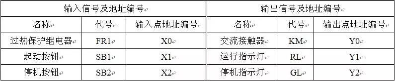 Table 1 PLC Control I/O Distribution Table in Continuous Control Circuit of Three-Phase AC Induction Motor
From Figure 1, it can be seen that by connecting the PLC’s I/O interface with external electrical components, the reliability of the system is improved, and the failure rate can be effectively reduced, making maintenance convenient. When the control program written into the PLC using programming software is executed, it can achieve automatic control of external electrical components and load motors. If you want to change the control method, you only need to modify the control program in the PLC, greatly improving debugging and modification efficiency.
Figure 2 shows the ladder diagram and statement table of the Mitsubishi FX2N series PLC for continuous control of the three-phase AC induction motor.
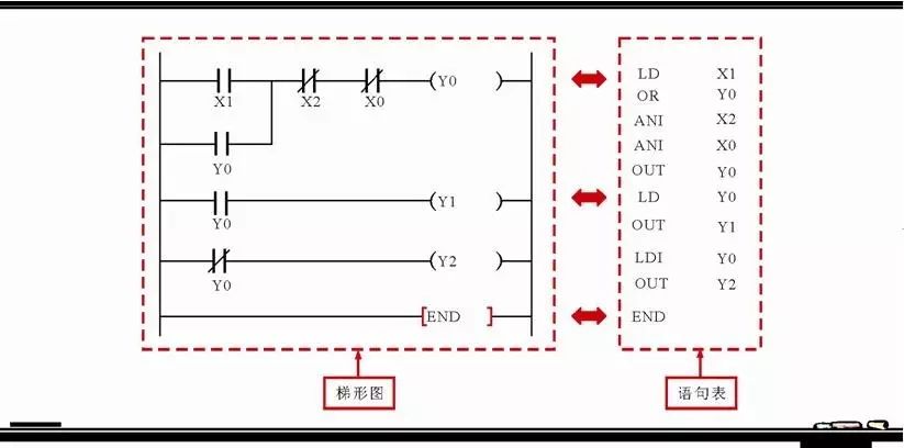 Figure 2 Ladder Diagram and Statement Table of Mitsubishi FX2N Series PLC for Continuous Control of Three-Phase AC Induction Motor
According to the ladder diagram, we can read the control process of this PLC. First, we can compare the PLC control circuit and the I/O distribution table, make appropriate textual annotations in the ladder diagram, and then analyze the starting and stopping control principles based on the operating actions.
1. Starting Process of Continuous Control Circuit of Three-Phase AC Induction Motor
Figure 3 shows the starting process of the three-phase AC induction motor under PLC continuous control.
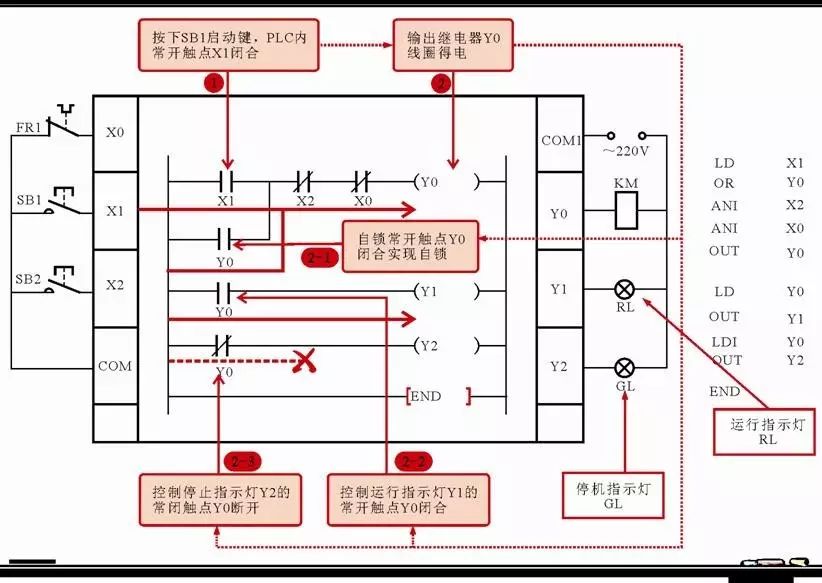 Figure 3 Starting Process of Three-Phase AC Induction Motor under PLC Continuous Control
1. When the start button SB1 is pressed, it sets X1 in the PLC to “1”, meaning that the normally open contact X1 closes.
1→2 The output relay Y0 coil is powered, controlling the PLC’s external AC contactor KM coil to be powered.
→2-1 The self-locking normally open contact Y0 closes, achieving self-locking function;
→2-2 The normally open contact Y0 closes to control the running indicator light Y1, powering Y1, and the running indicator light RL lights up.
→2-3 The normally closed contact Y0 opens to control the stop indicator light Y2, de-energizing Y2, and the stop indicator light GL goes out.
Note
The normally open contact Y0 closes for self-locking, mainly to maintain the output relay Y0 coil in a powered state, even if the start button is released, the motor will still keep running. Therefore, the start button is often a momentary switch, pressed once to start, and when released, the motor still keeps running, effectively reducing electrical losses and improving safety and reliability.
2. Stopping Process of Continuous Control Circuit of Three-Phase AC Induction Motor
When using the Mitsubishi FX2N series PLC continuous control circuit to stop the motor, the following operations can be performed:
When the stop button SB2 is pressed, it sets X2 in the PLC to “0”, meaning that the normally closed contact X2 opens, causing the output relay Y0 to lose power, and the de-energization of this relay will trigger the following actions:
-
The output relay Y0 loses power, and the corresponding contact actions, that is, the normally open and normally closed contacts Y0 reset, Y1 loses power, Y2 is powered, the running indicator light RL goes out, and the stop indicator light GL lights up.
-
The PLC external AC contactor coil KM loses power. With KM losing power, the normally open contact KM-1 in the main circuit opens, and the motor stops running.
Ladder Diagram and Statement Table of PLC in Y-Δ Soft Start Control Circuit of Three-Phase AC Induction Motor
The Y-Δ soft start control of the three-phase AC induction motor refers to the control method where the motor is first started with its windings connected in Y shape and then switched to Δ connection for operation through the control circuit. Before learning the control, we first need to understand what the Y (star) and Δ (triangle) connections of the three-phase motor windings are, as shown in Figure 4.
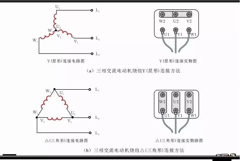 Figure 4 Y (Star) and Δ (Triangle) Connection of Three-Phase Motor Windings
Figure 5 shows the PLC ladder diagram and statement table for Y-Δ soft start control of three-phase AC motors, and Table 2 lists its I/O address distribution table.
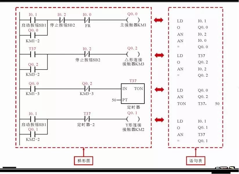 Figure 5 PLC Ladder Diagram and Statement Table for Y-Δ Soft Start Control of Three-Phase AC Motor
 Table 2 PLC Control I/O Address Distribution Table in Y-Δ Soft Start Control of Three-Phase AC Motor
Combining the I/O address distribution table, first understand the meaning of each contact and symbol in the ladder diagram or statement table, and analyze by combining the ladder diagram with the statement table.
1. Control Process of Y-Δ Soft Start of Three-Phase AC Induction Motor
Figure 6 shows the control process of the three-phase AC induction motor’s windings connected in Y for soft start after pressing the start button SB1.
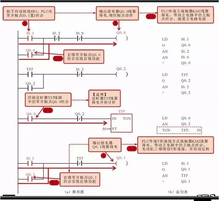 Figure 6 Control Process of Y Connection Soft Start of Three-Phase AC Induction Motor
1. When the start button SB1 is pressed, it sets the normally open contact I0.1 in the PLC program to “1”, meaning that the normally open contact I0.1 closes.
1→2 The output relay Q0.0 coil is powered.
→2-1 The self-locking normally open contact Q0.0 closes to achieve self-locking function;
→2-2 The normally open contact Q0.0 closes to control the timer T37’s normally open contact, powering the timer T37 coil and starting timing;
→2-3 The control PLC external power supply main contactor KM1 coil is powered, driving the main contact in the main circuit to close, connecting the main power supply to the motor.
1→3 The output relay Q0.1 coil is also powered.
→3-1 The self-locking normally open contact Q0.1 closes to achieve self-locking function;
→3-2 The control PLC external Y connection contactor KMY coil is powered, and the three-phase windings of the motor are connected in Y, starting operation.
Next, the three-phase AC induction motor windings will automatically switch to Δ connection for operation, as shown in Figure 7.
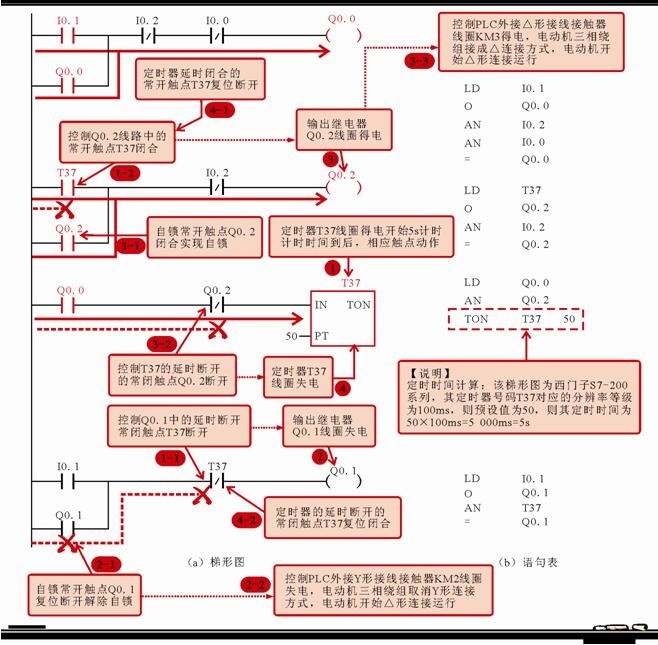 Figure 7 Automatic Switching of Three-Phase AC Induction Motor Windings to Δ Connection
1. When the timer T37 coil is powered and starts the timing of 5 seconds, the relevant contact actions occur.
→1-1 The normally closed contact T37 of the output relay Q0.1 opens, causing the output relay Q0.1 coil to lose power;
→1-2 The normally open contact T37 of the output relay Q0.2 closes.
1-1→2 The output relay Q0.1 coil loses power.
→2-1 The self-locking normally open contact Q0.1 resets and releases the self-locking;
→2-2 The control PLC external Y connection contactor KMY coil loses power, cancelling the Y connection of the motor windings.
1-2→3 The output relay Q0.2 coil is powered.
→3-1 The self-locking normally open contact Q0.2 closes, achieving self-locking function;
→3-2 The control timer T37’s normally closed contact Q0.2 resets, preparing for the next power on for Q0.1;
2. Control Process of Stopping the Three-Phase AC Induction Motor
If you want to stop the three-phase AC induction motor, you can control it using the stop button SB2, as shown in Figure 8.
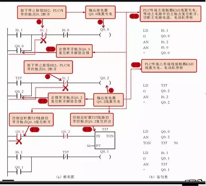 Figure 8 Stopping the Three-Phase AC Induction Motor
1. When the stop button SB2 is pressed, it sets the normally closed contact I0.2 in the PLC program to “0”, meaning that the normally closed contact I0.2 opens.
1→2 The output relay Q0.0 coil loses power.
→2-1 The self-locking normally open contact Q0.0 resets and releases the self-locking;
→2-2 The control timer T37’s normally open contact Q0.0 resets;
→2-3 The control PLC external power supply main contactor KM1 coil loses power, cutting off the main circuit power supply, and the motor stops running.
1→3 The output relay Q0.2 coil loses power.
→3-1 The self-locking normally open contact Q0.2 resets and releases the self-locking;
→3-2 The control timer T37’s normally closed contact Q0.2 resets, preparing for the next power on for the timer T37;
→3-3 The control PLC external Δ connection contactor KM3 coil loses power, stopping the motor.
In summary, the function of the PLC ladder diagram and statement table for the Y-Δ soft start control of the three-phase AC induction motor is to achieve the Y connection method when starting, and after a delay, automatically switch to the Δ connection method for operation.
Ladder Diagram and Statement Table of PLC in Automatic Cycle Control Circuit of Three-Phase AC Induction Motor
Automatic cycle control of the three-phase AC induction motor refers to the method where the motor automatically realizes forward and reverse cycle control under the action of limit switches.
Figure 9 shows the PLC ladder diagram and statement table in the automatic cycle control of the three-phase AC induction motor, and Table 3 lists its I/O address distribution table.
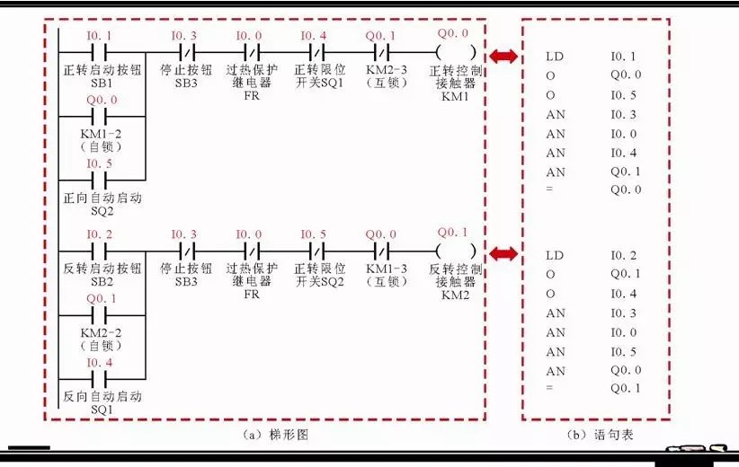 Figure 9 PLC Ladder Diagram and Statement Table in Automatic Cycle Control of Three-Phase AC Induction Motor
 Table 3 PLC Control I/O Address Distribution Table in Automatic Cycle Control of Three-Phase AC Induction Motor
Combining the I/O address distribution table, first understand the meaning of each contact and symbol in the ladder diagram or statement table, and analyze by combining the ladder diagram with the statement table.
1. Control Process of Forward Start Button SB1 for Motor M1 to Automatic Reverse
Figure 10 shows the control process of the motor starting to automatic reverse when the start button SB1 is pressed.
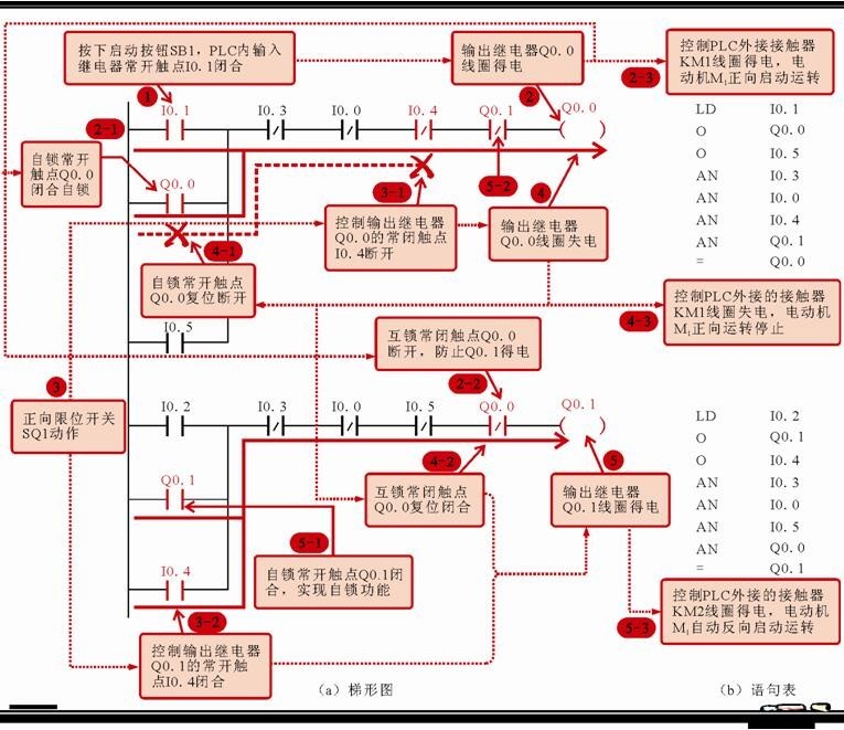 Figure 10 Control Process of Motor M1 Starting to Automatic Reverse
1. When the start button SB1 is pressed, it sets the normally open contact I0.1 in the PLC program to “1”, meaning that the normally open contact I0.1 closes.
1→2 The output relay Q0.0 coil is powered.
→2-1 The self-locking normally open contact Q0.0 closes, achieving self-locking function;
→2-2 The control output relay Q0.1’s normally closed contact Q0.0 opens, preventing Q0.1 from being powered, achieving interlocking;
→2-3 The control PLC external AC contactor KM1 coil is powered, driving the main contact in the main circuit to close, connecting the motor M1 to the forward power supply, and the motor M1 starts to run forward.
3. When the motor runs to the forward limit switch SQ1 position, SQ1 is triggered under pressure, and the corresponding input relay contact I0.4 in the PLC program acts.
→3-1 The normally closed contact I0.4 of the output relay Q0.0 opens;
→3-2 The normally open contact I0.1 of the output relay Q0.1 closes;
3-1→4 The output relay Q0.0 coil loses power.
→4-1 The self-locking normally open contact Q0.0 resets and releases the self-locking;
→4-2 The control output relay Q0.1’s normally closed contact Q0.0 resets, preparing for next power on for Q0.1;
3. Stopping Control Process of Motor M2 and Starting Control Process of Motor M1
When two motors are running alternately, that is, stopping motor M1 and starting motor M2 can be completed through the following control, as shown in Figure 14.
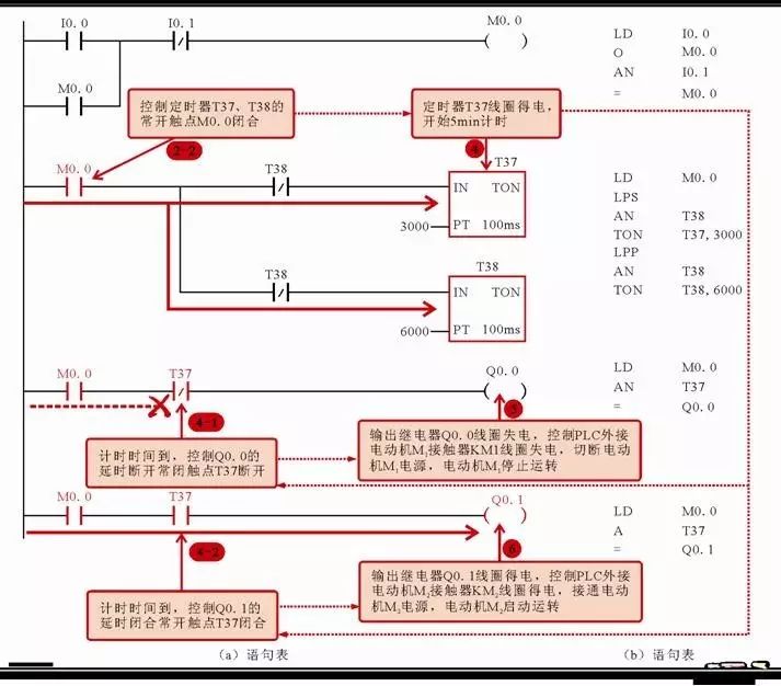 Figure 14 Alternating Operation of Two Motors
2-2→4 The timer T37 coil is powered, starting timing.
→4-1 When the timing time is up (delay 5min), the control output relay Q0.0’s normally closed contact T37 opens.
→4-2 When the timing time is up (delay 5min), the control output relay Q0.1’s normally open contact T37 closes.
4-1→5 The output relay Q0.0 coil loses power, controlling the PLC external motor M1’s contactor KM1 coil to lose power, driving the main contact in the main circuit to open, cutting off the power supply to motor M1, and motor M1 stops running.
4-2→6 The output relay Q0.1 coil loses power, controlling the PLC external motor M2’s contactor KM2 coil to be powered, driving the main contact in the main circuit to close, connecting the power supply to motor M2, and motor M2 starts running.
3. Stopping Control Process of Motor M2 and Starting Control Process of Motor M1
When motor M2 needs to stop and motor M1 needs to start, it can be achieved through timer control, as shown in Figure 15.
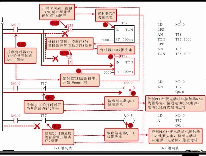 Figure 15 Stopping Motor M2 and Starting Motor M1
2-2→7 The timer T38 coil is powered, starting timing.
→7-1 When the timing time is up (delay 10min), the control timer T37’s normally closed contact T38 opens.
→7-2 When the timing time is up (delay 10min), the control timer T37’s normally closed contact T38 opens.
7-3→8 The timer T37 coil loses power.
→8-1 The control output relay Q0.0’s normally closed contact T37 resets and closes.
→8-2 The control output relay Q0.1’s normally open contact T37 resets and opens.
8-2→9 The output relay Q0.1 coil loses power.
→9-1 The control PLC external motor M2’s contactor KM2 coil loses power, driving the main contact in the main circuit to open, cutting off the power supply to motor M2, and motor M2 stops running.
When two motors need to stop running, press the stop button SB2, which sets the normally closed contact I0.1 in the PLC program to “0”, meaning that the normally closed contact I0.1 opens, causing the auxiliary relay M0.0 coil to lose power, resetting the contacts, and the timers T37, T38, and output relays Q0.0, Q0.1 coils all lose power, controlling the PLC external motor contactor coils to lose power, driving the main contacts in the main circuit to open, cutting off the power supply to the motors, and the motors stop cyclic operation.


(-END-)
Excerpt from “Learn PLC and PLC Circuits Easily” edited by Han Xuetao
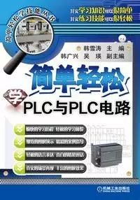
The industry standards and professional requirements for reading and applying PLC and PLC circuits are integrated into the structure of the book, while emphasizing a step-by-step approach to knowledge and focusing on situational classroom-style oral expression and readability.
 Long press the QR code to recognize and purchase
Previous Highlights
Essential Rules for Electricians: Structure, Working Principle, and Selection Criteria of Leakage Protectors
Secrets for Troubleshooting Electronic Products! Effective troubleshooting methods, which methods do you think are the best?
Zhang Baifan: What are the differences between circuit breakers, isolators, and load switches?
Professional AS-i Bus Technology Explanation: AS-i Working Modes and Communication Process