Safety Analysis: Should PLC Stop and Emergency Stop Buttons Use Normally Open or Normally Closed Contacts?
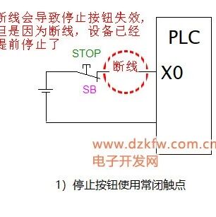
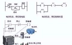
In traditional control circuits, such as forward and reverse control, star-delta starting, etc., the start, forward, and reverse buttons used in these circuits are all normally open contacts, while the stop button uses normally closed contacts. However, after learning about PLCs, you will encounter a question: Should the stop or emergency stop button of a … Read more