Have you ever felt lost in a massive PLC program? Have you ever had to modify an entire project due to a change in an IO point address? Have you ever had to sift through all the code just to find a single variable while debugging a device?
If you are facing these challenges, then the **PLC Modular Programming Method** introduced today will completely change your programming mindset!
## Why is Modular Programming Necessary?
In traditional PLC programming, we often encounter:
– Code redundancy, where the same functionality appears in multiple places
– Maintenance difficulties, where modifying one area may cause errors in multiple locations
– Low team collaboration efficiency, with no unified standards
– High costs for program migration during equipment upgrades
## Solution: UDT-Based Modular Programming
### Step 1: Standardize Data Structures
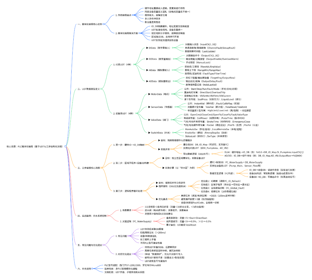
Use **User Defined Data Types (UDT)** to create standardized data structures for each type of device:
– **IO Layer UDT**: DIData, DOData, AIData, AOData
– **Device Layer UDT**: MotorData (including direct start/inverter/submersible pumps), SensorData (including cumulative/non-cumulative flow), ValveData (including solenoid valves/switching valves/regulating valves), SwitchData
### Step 2: Three-Layer Architecture Design
**1. Data Layer (IO_DB)**
Create a separate hardware mapping area to manage all physical IO addresses uniformly, achieving complete decoupling of hardware and logic.
**2. Device Layer (Device DB)**
Divide by process area, using device UDT to instantiate specific devices in each subroutine, achieving encapsulation and reuse of device control.
**3. Logic Layer (Main Program)**
Handle cross-area coordination logic, focusing on process implementation without worrying about underlying hardware details.
### Step 3: Standardized Programming Process
1. **Hardware Mapping**: Map physical IO to IO_DB
2. **Area Programming**: Implement device control logic in respective subroutines
3. **Loop Processing**: Organize all modules in the main program to achieve a complete process
## Benefits of This Method
**For individual developers:**
– Coding efficiency improved by over 50%
– Debugging time significantly reduced
– Code quality greatly enhanced
**For teams:**
– New members can quickly get up to speed
– Seamless project handover
– High code reuse rate
**For projects:**
– Reduced maintenance costs in the later stages
– Easier equipment upgrades and modifications
– Higher system stability
## Practical Case Study
After adopting this method in a large water treatment project:
– Programming time was reduced from 3 weeks to 1 week
– Debugging issues decreased by 70%
– Over 60% of the code was reused in subsequent similar projects
## Take Action
Modular programming is not a complex theory, but an engineering mindset. Start using this method in your next project:
1. Start by defining core UDTs
2. Establish the IO mapping area
3. Divide functional areas
4. Implement device control logic
**Excellent programmers write code, outstanding engineers build systems.**
Want to get detailed UDT definition examples and program architecture diagrams? Feel free to leave a message in the comments section 【Contact】【Case】, and we will send you a detailed information package!
—
【Follow us for more industrial automation insights】