For more exciting content, click to follow and unlock more PLC technical knowledge!
In industrial automation control, managing communication for multiple inverters is a common issue. How can we efficiently and stably achieve polling control? This article will guide you step by step!
011. System OverviewPolling Control Technology allows centralized management of multiple inverters through a single RS-485 bus, suitable for industrial automation scenarios that require simplified wiring and cost reduction. This solution uses a Mitsubishi PLC paired with a BD board to achieve alternating communication and control of two Haipumont inverters.022. Hardware Configuration
-
Main Controller: Mitsubishi FX series PLC (with RS-485 BD board)
-
Execution Devices: Two Haipumont inverters (supporting Modbus RTU)
-
Auxiliary Components: 110Ω terminal resistor (anti-interference)
033. Hardware Wiring
3.1 Communication Line Connection
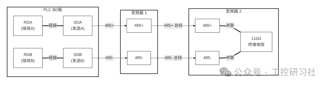 Core Wiring:
-
RDA/SDA → 485+; RDB/SDB → 485-
-
Parallel 110Ω terminal resistor between the master station and the last slave station
-
Shielding layer grounded at one end, use twisted pair shielded cable (≤100 meters)
044. Parameter Configuration
4.1 Inverter Parameters

| Parameter Code | Set Value | Description |
|---|---|---|
| F00.10 | 02 | Communication Control Mode |
| F00.11 | 02 | Communication Set Frequency |
| F17.00 | 1 | Even Parity (1 Start Bit/8 Data Bits) |
| F17.01 | 3 | Baud Rate 9600bps |
| F17.02 | 1/2 | Station Number Setting (Station 1/2) |
4.2 PLC Communication Parameters
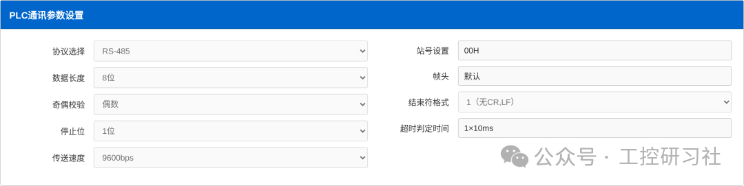
-
Protocol: RS-485 | Data Length: 8 bits | Parity: Even
-
Stop Bits: 1 bit | Baud Rate: 9600bps | Station Number: 00H | Timeout: 10ms
055. Polling Control Logic
5.1 Station Number Switching Principle
Realized through the Station Number Register D0, achieving a cycle of 1→2→1, with the communication completion flag M8123 triggering the station number increment.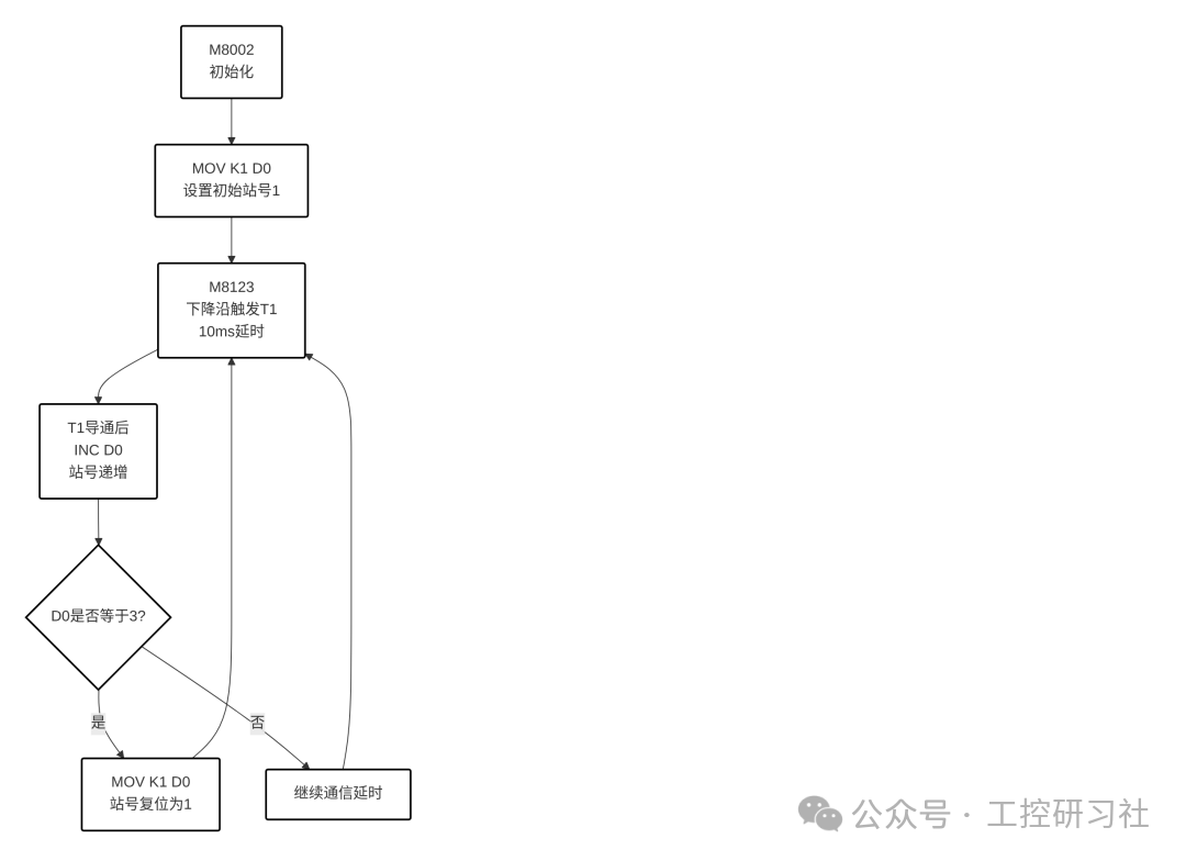 Core Program:plaintext
M8002 MOV K1 D0 // Initialize Station Number=1 M8123 T1 K10 // Communication Completion Delay 10ms T1 INC D0 // Station Number Increment D0=3 MOV K1 D0 // Station Number Reset5.2 Communication Timing
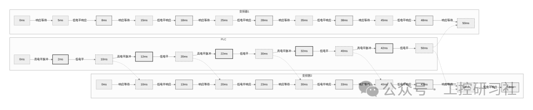
-
Single Station Communication Cycle: 20ms | Polling Cycle: 40ms
-
Communication Gap: 10ms (to avoid data conflict)
066. Core Program Design
6.1 Frequency Read/Write Control
Frequency Write (Address H3201):plaintext
M8161 // Enable 8-bit mode MOV D18 D20 // Touch screen frequency → Send buffer RS D0 K6 D20 // Send data M8122 // Trigger communicationStatus Read (Address H3310):plaintext
MOV H3310 D2 // Read address setting RS D0 K6 D20 // Send request M8123 // Wait for completion6.2 Data Processing
8-bit communication data needs to be restored through byte swapping:plaintext
SWAP D103 // High and low byte swap ADD D103 D104 D200 // Merge 16-bit data| Raw Data (Hex) | Processed Data (Decimal) | Actual Frequency (Hz) |
|---|---|---|
| D103=00,D104=64 | 0064H=100 | 10.0 |
| D103=01,D104=F4 | 01F4H=500 | 50.0 |
087. Debugging Key Points
| Debugging Steps | Key Check Items | Common Problem Solutions |
|---|---|---|
| 1. Hardware Check | Wiring correctness, terminal resistor connection | Communication timeout → Check wiring/parameters |
| 2. Parameter Verification | Baud rate/parity/station number consistency | Data garbled → Unify communication parameters |
| 3. Polling Test | D0 value 1-2 cycle switching | Polling stutter → Increase T1 delay (>10ms) |
| 4. Function Verification | Touch screen frequency setting response | – |
098. Technical Summary
-
Wiring Specifications: 485+/- differential signals must be twisted pair shielded, terminal resistors cannot be omitted
-
Parameter Matching: Baud rate/parity/data bits of master and slave stations must be completely consistent
-
Core Program: Achieve polling through station number increment and reset, communication gap must be ≥10ms
-
Data Processing: 8-bit mode requires byte swapping and merging operations

Scan to receive classic PLC cases and source programs for free

 Scan to receiveElectrical/PLC/Inverter learning materials
Previous Recommendations
[8 Weeks to High Salary] Transform from Zero to PLC Expert! The “Golden Bowl” of Manufacturing Industry Awaits You!
The Journey of Becoming a PLC Engineer with a Monthly Salary of 30K+! A Must-Read for Industrial Control Professionals
400-page Electrical Control PPT + 900+ Practical Circuit Cases, Essential Resource Pack for Engineers!
[Animated Learning] 18 PLC Dynamic Demonstrations, Understand Industrial Automation Control from Scratch
37 Animated Diagrams Explaining Sensor Working Principles, Finally Understood!
Come and Challenge! Hundreds of Mechanical Dynamic Diagrams! Those Who Understand Are Experts!
S7-200SMART PLC Advanced Applications: Multiple Calls of Single Button Start/Stop Function
How to Write a Good PLC Alarm Program? A Practical Guide from Beginner to Expert
Siemens PLC Programming Software Selection Guide: A Comprehensive Strategy from 200SMART to 1500
 Share
Share Collect
 View
View Like
Like