
In a TN-C-S system, when the PEN line within a building needs to be separated into PE and N lines, many people are puzzled: should the neutral busbar be connected first, or the PE busbar? This is quite a significant question!
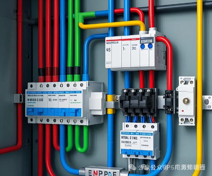
In a TN-C-S system, the distribution trunk enters the building and connects directly to the main distribution box. The busbars in the main distribution box include L1, L2, L3, N, and PE, where the N and PE busbars are usually installed at the bottom of the distribution box for convenient wiring operations. It is particularly important to note that the PEN line must first be connected to the PE busbar, and then connected to the neutral busbar via a wire.
Why is this necessary? The reason is simple.
If the connection wire from the PE busbar to the N busbar becomes loose, resulting in a disconnection of the neutral line, the equipment will immediately stop functioning properly. This type of fault is easily detectable and can be repaired promptly, preventing electrical safety incidents. However, if the PEN line is connected to the neutral busbar first, and the same loose connection occurs, the electrical system will lose its protective grounding function.
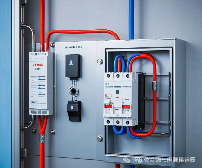
At this point, the equipment may still operate normally, which poses a significant safety risk because the electrical equipment lacks protective grounding. This could potentially lead to electric shock incidents. Therefore, connecting the PEN line in the correct order is a crucial step in ensuring electrical safety.
※ Further Reading:
According to the current national standard “Low Voltage Distribution Design Specification” (GB50054), there are three grounding forms in low voltage distribution systems: IT, TT, and TN. The first letter reflects the relationship between the power source and the ground: T indicates that the neutral point of the power transformer is directly grounded; I indicates that the neutral point of the power transformer is not grounded or is grounded through high impedance.
The second letter indicates the relationship between the exposed conductive parts of the electrical installation and the ground: T indicates that the exposed conductive parts of the electrical installation are directly grounded, and the grounding point is electrically independent from the grounding point of the power source; N indicates that the exposed conductive parts of the electrical installation are directly electrically connected to the grounding point of the power source. In subsequent letters, S indicates that the protective line (PE line) and neutral line (N line) are completely separated; C indicates that the protective line and neutral line are combined; C-S indicates that part is combined and part is separated.
The differences between TN, TT, and IT grounding systems:
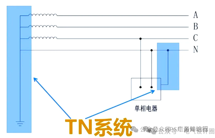
TN System: In a TN system, the metal shell of the user’s electrical equipment is connected to the neutral point of the power source. If the phase line contacts the shell, the fault current returns to the power source through the PE line, and the overcurrent protection device in the distribution circuit quickly disconnects the fault, achieving both overcurrent protection and grounding fault protection. This system is widely used in indoor power supply in buildings, combined with indoor equipotential bonding to ensure stable and safe low voltage power supply.
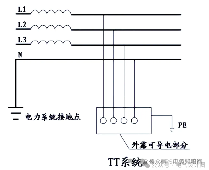
TT System: In a TT system, the metal shell of the user’s electrical equipment is directly grounded at the device. If the phase line contacts the shell, the fault current flows back to the neutral point of the power source through the ground. Since the fault current is relatively small, it may not trigger the overcurrent protection device, so an additional RCD is required to provide grounding fault protection. The TT system is commonly used in outdoor power supply situations without equipotential environments to ensure power supply safety.
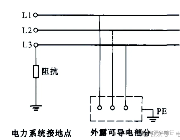
IT System: In an IT system, the neutral point on the power side is not grounded, and the metal shell of the user’s electrical equipment is grounded. In the event of a phase line contacting the shell, the fault current cannot return directly to the power source, but only forms a loop through the capacitive currents of the other two phases to ground. The fault current is small, and the fault voltage generated on the equipment shell is low, which can avoid electric shock, and there is no need to immediately disconnect the power supply. Therefore, the IT system is often used in scenarios with extremely high reliability requirements for power supply, such as hospital surgical equipment and some national fire protection equipment, ensuring that critical equipment does not lose power.
 Disclaimer: Due to some articles being reprinted too many times, we apologize for not being able to find the original author. The articles do not represent the views of this site and are for reference only. Copyright belongs to the original author. If there is any infringement, please contact us for deletion; Source: Internet
We invite you to “Read the full article” or “Scan the QR code below” to join the【Factory Knowledge Base】knowledge community, unlocking the full skill package for factory operations! Helping you double your salary!!
VIP Member Premium Resources
- Photovoltaic module and photovoltaic power station full lifecycle management textbook (involving production, installation, debugging, training, etc.)
- Factory operations (clean room, compressed air, special gases, pure water, electricity, secondary distribution, chemicals, vacuum, PCW, etc.) training materials
- Summary of factory operations infrastructure maintenance 3P (MOP, SOP, EOP) documents, with methods for obtaining at the bottom of the article
- Essential document checklist for factory operations maintenance
- Special article on energy-saving technologies for factory operations