1. Visual Inspection
In simple terms: A Hall effect current sensor is a “magnetic-electric” converter that can linearly convert the strength of a magnetic field into a voltage signal. Check the sensor casing for burn marks, cracks, deformation, or pin corrosion and other obvious physical damage. Overheating often causes discoloration or bulging of the casing.
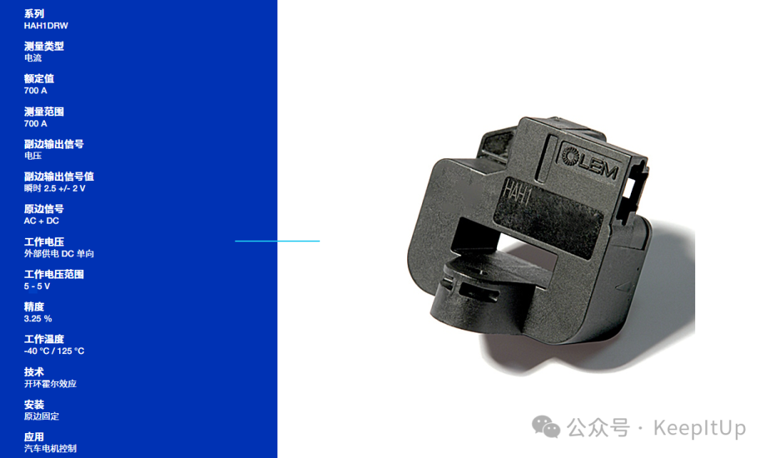
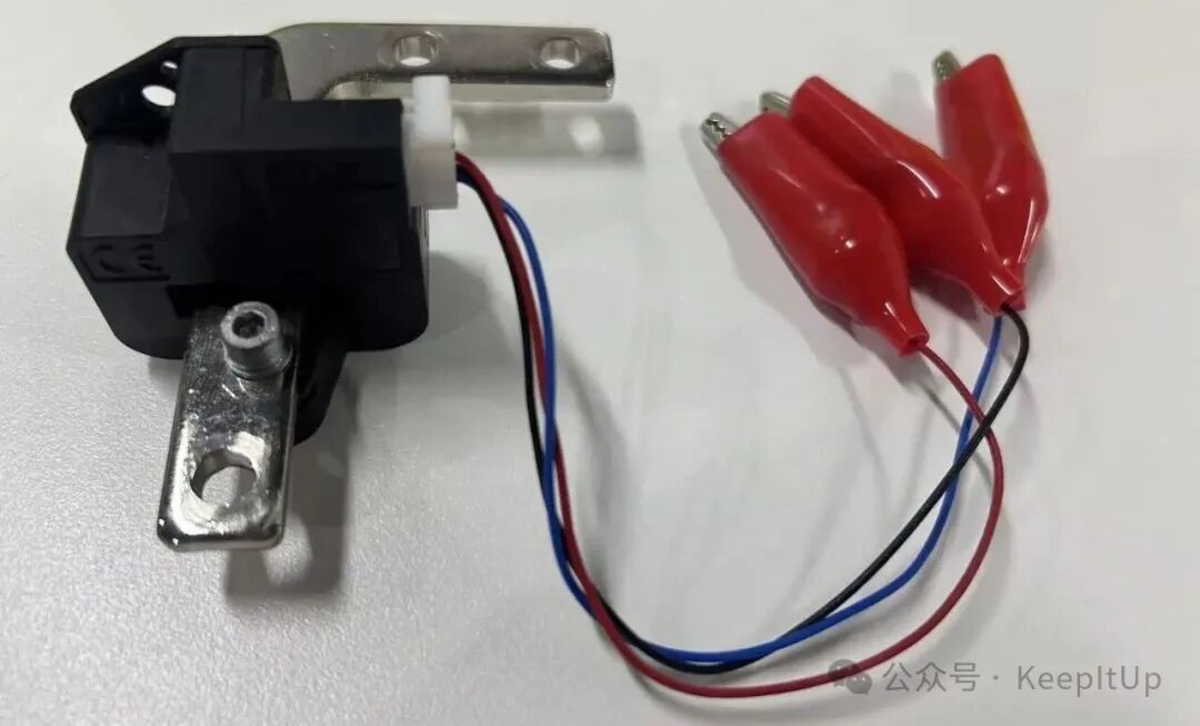 As shown in the figure, this is a LEM brand current sensor, model HAH1DRW 100-S.2. Data Collection
-
Data Collection: Record the sensor model and find its datasheet. This is the most critical step, as the datasheet will provide all key parameters, such as:
-
Supply Voltage: e.g., ±12V, ±15V, 5V, 24V, etc.
-
Output Type: Voltage output or current output (e.g., 4-20mA)?
-
Zero Output: The output voltage when no current is being measured, usually 2.5V (half-range) or 0V.
-
Measurement Range: e.g., ±50A, ±200A, etc.
-
Ratio: The relationship between the output voltage and the measured current, such as 50A corresponding to ±4V.
3. Static Testing
Essential Tools: Multimeter, adjustable power supply
Steps:
-
Correct Wiring:
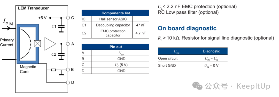
(1) According to the datasheet, provide the sensor’s power pins (Vcc/Vdd and GND/Com) with a precise and stable rated voltage of +5V. Note: The polarity must not be reversed, or the sensor may be damaged instantly!
(2) Set the multimeter to the voltage range, preparing to measure the output voltage.
2. Measure Zero Output:
(1) Ensure the current-carrying wire passes through the center hole of the sensor, and there is no current flowing through the wire at this time.
(2) Measure the voltage between the output pin and GND.
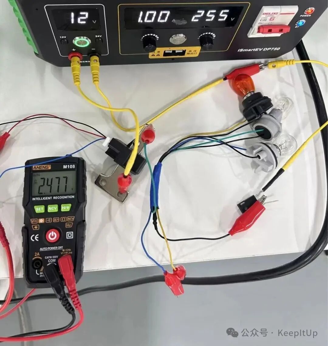
(3) Determine: For sensors with a zero point at half-range (e.g., powered by ±12V, the zero point should be 0V; powered by 5V, the zero point is usually 2.5V), the reading should be within the range specified in the datasheet (usually within ±25mV). If the deviation is large (e.g., powered by 5V, the output is 0V or 5V), the sensor is likely damaged.
4. Dynamic Testing
Essential Tools: Multimeter, adjustable load (e.g., electronic load, high-power resistor), high-power adjustable power supply (or battery)
Steps:
1. Set Up the Test Circuit:
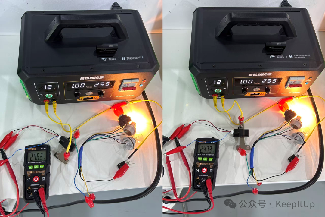
(1) Use a power bulb (e.g., 12V/21W) as a load, in series with a power supply to form a current loop.
(2) Pass the wires of this loop through the center hole of the Hall sensor. Ensure the wires are centered, and the current direction is consistent with the sensor’s marked direction.
(3) Measure and Determine:
① When applying +1A current, theoretical output = 2.477V + (1A * 0.004V/A) = 2.482V.
② When applying -1A current, theoretical output = 2.477V + (-1A * 0.004V/A) = 2.473V.
③ Use the multimeter to measure the output voltage of the sensor. (Slight deviations can ignore the 1A current corresponding to 0.004V)
(4) If the actual measured value deviates significantly from the theoretical calculated value (beyond the accuracy error specified in the datasheet, such as 3.25%), the sensor’s linearity is poor or it is damaged..
(5) Change the magnitude and direction of the current; the output should be able to change linearly and smoothly. If there are jumps, the output remains unchanged, or it cannot follow the changes, the sensor is damaged.
 2. If you are unsure how to measure, please refer to the detailed video tutorial below: