“This article introduces the Wi-Fi UDP communication of the ESP32-S3. It is based on a dual-core processor, supports relevant protocols, and implements UDP transmission through the lwIP protocol stack. The article explains the working principle and process, provides program design code, and demonstrates test results, highlighting its application in scenarios such as the Internet of Things.”
01
—
Introduction
The ESP32-S3 is a high-performance Wi-Fi and Bluetooth dual-mode communication chip launched by Espressif Systems, based on a dual-core Xtensa LX7 processor with a maximum operating frequency of 240MHz. It integrates Wi-Fi and Bluetooth 5.0 functionalities, supports 802.11 b/g/n protocols, and can meet the wireless communication needs of various IoT and embedded devices. UDP (User Datagram Protocol) is a connectionless network transmission protocol suitable for scenarios with high real-time requirements, such as audio and video streaming.
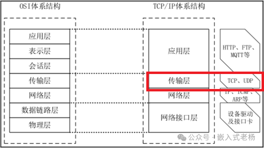
In the TCP/IP architecture, UDP (User Datagram Protocol) is located at the transport layer.
The TCP/IP architecture is divided into application layer, transport layer, network layer, and network interface layer. The main function of the transport layer is to provide services for communication between processes on two hosts, responsible for end-to-end data transmission, ensuring that data can be correctly transmitted from the source application to the target application. Besides UDP, another important protocol at this layer is TCP (Transmission Control Protocol). In comparison, UDP is connectionless, does not guarantee reliable transmission, order, or integrity of data, but has higher transmission efficiency and lower latency; while TCP is connection-oriented and provides reliable data transmission services.
02
—
Working Principle
1.Wi-Fi Connection
The Wi-Fi functionality of the ESP32-S3 is based on the IEEE 802.11 standard, achieving wireless signal reception and transmission through the RF front end, baseband processor, and MAC control unit. When the Wi-Fi module is operational, the RF front end is responsible for sending and receiving signals, the baseband processor performs modulation and demodulation, the MAC layer processes data packets, and finally communicates with the microcontroller through the host interface.
2.UDP Data Transmission
UDP provides connectionless network services, sending data in the form of datagrams, which do not guarantee reliability but are more efficient. In the ESP32-S3, UDP data transmission is implemented through the lwIP protocol stack, which supports TCP/IP, UDP, and other protocols. Developers can use the APIs provided by ESP-IDF to create UDP sockets and send and receive data through the sendto and recvfrom functions.
3.Hardware Architecture
The ESP32-S3 chip integrates a dual-core processor, Wi-Fi and Bluetooth modules, various peripheral interfaces, and rich memory resources. Its hardware architecture includes:
-
Dual-core Xtensa LX7 processor: provides high-performance processing capability.
-
Wi-Fi and Bluetooth modules: support 2.4GHz band Wi-Fi and Bluetooth 5.0.
-
Peripheral interfaces: including GPIO, SPI, I2C, ADC, etc., for connecting sensors, displays, and other devices.
-
Memory resources: provide sufficient RAM and ROM to support complex program execution.
4.Wi-Fi Protocol
The ESP32-S3 supports the IEEE 802.11 b/g/n protocol and can operate in the 2.4GHz band. Its Wi-Fi protocol stack includes the physical layer (PHY), MAC layer, and network layer, which are responsible for wireless signal transmission, media access control, and IP addressing functions, respectively.
5.UDP Protocol
UDP is a connectionless transport layer protocol suitable for scenarios requiring fast transmission without guaranteeing data reliability. In the ESP32-S3, the UDP protocol is implemented through the lwIP protocol stack, supporting the sending and receiving of datagrams. UDP does not guarantee the order and integrity of data but has lower transmission latency, making it suitable for applications with high real-time requirements.
03
—
Design Process
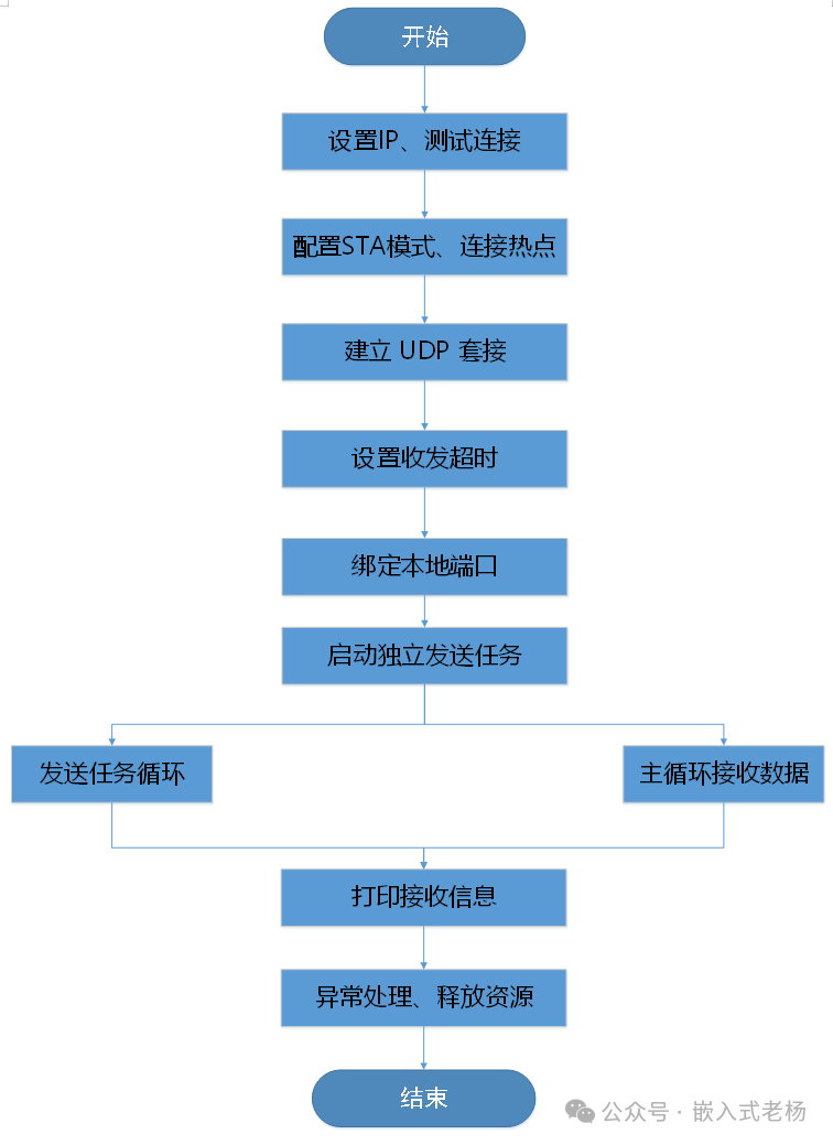
①. Set IP, Test Connection
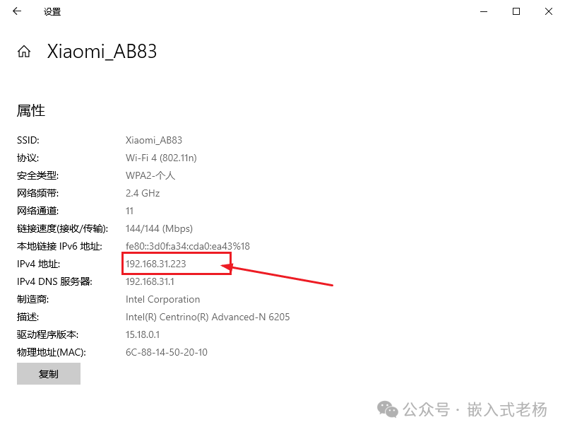
In the network connection settings, query the main IP as shown in the figure below:
Read the IP of the ESP32 development board through the program as shown in the figure below:

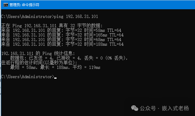
The terminal test computer is connected to the ESP32 development board, and the connection is normal:
②. Configure STA Mode, Connect to Hotspot
Initialize NVS:
First, call nvs_flash_init() to provide persistent space for saving calibration and configuration data for the Wi-Fi driver.
Create Event Loop and Default Network Card:
Establish the system event bus and STA network interface through esp_netif_init(), esp_event_loop_create_default(), and esp_netif_create_default_wifi_sta().
Install Wi-Fi Driver:
Load the Wi-Fi driver into memory using esp_wifi_init(&cfg) to prepare for subsequent connections.
Register Event Callback:
Bind the callback functions for WIFI_EVENT and IP_EVENT using esp_event_handler_register() to capture events such as connection, disconnection, and obtaining IP in real-time.
Set STA Parameters and Start:
Specify SSID/password and enter STA mode using esp_wifi_set_mode(), esp_wifi_set_config(), and esp_wifi_start(), starting the air scan and handshake.
Wait for Successful Connection:
Use xEventGroupWaitBits() to block and wait for WIFI_CONNECTED_BIT to be set, confirming that the hotspot is connected and the IP is obtained before continuing with business logic.
③. UDP Configuration and Data Transmission Process
Establish UDP Socket:
Call socket(AF_INET, SOCK_DGRAM, IPPROTO_UDP) to create a UDP socket, obtaining the global descriptor g_sock_fd.
Set Send/Receive Timeout:
Use setsockopt(SO_RCVTIMEO) to set the receive timeout to 1 second to avoid permanent blocking.
Bind Local Port:
Fill the sockaddr_in structure with the local address INADDR_ANY and port 8080, then bind() to let the kernel fix the local listening port.
Start Independent Sending Task:
Create a FreeRTOS task using xTaskCreate(udp_send_task) to automatically send data to the target IP once per second.
Sending Task Loop:
In udp_send_task(), loop: delay 1 second → construct target address → sendto() sends “ESP32-S3 send data……\r\n”.
Main Loop Receives Data:
lwip_demo() main loop blocks on recvfrom(), once data arrives, it reads and prints the source IP, port, and content.
Print Received Information:
After receiving data, append \0 to the end of the buffer and call ESP_LOGI() to output RX[source IP:source port]: content.
Error Handling, Release Resources:Immediately close(g_sock_fd) and print an error when creation, binding, or sending fails to ensure timely resource release.
04
—
Program Design
Function Description:
Implement the Wi-Fi STA mode connection and UDP bidirectional communication of the ESP32-S3. Initialize the Wi-Fi connection hotspot, create an LED blinking task, bind the local port through the UDP socket, periodically send data to the target IP, and continuously receive UDP data from external sources and print it.
Main Function:
void app_main(void){    esp_err_t ret = nvs_flash_init();    if (ret == ESP_ERR_NVS_NO_FREE_PAGES || ret == ESP_ERR_NVS_NEW_VERSION_FOUND) {        ESP_ERROR_CHECK(nvs_flash_erase());        ESP_ERROR_CHECK(nvs_flash_init());    }
    led_init();    usart_init(115200);
    wifi_sta_init();      /* Must obtain IP first */
    /* Create LED task */    xTaskCreate(led_task, "led_task", LED_STK_SIZE, NULL, LED_TASK_PRIO, &LEDTask_Handler);
    /* Start UDP send/receive */    lwip_demo();}
WI-FI Initialization:
void wifi_sta_init(void){    wifi_event = xEventGroupCreate();    ESP_ERROR_CHECK(esp_netif_init());    ESP_ERROR_CHECK(esp_event_loop_create_default());    esp_netif_create_default_wifi_sta();
    wifi_init_config_t cfg = WIFI_INIT_CONFIG_DEFAULT();    ESP_ERROR_CHECK(esp_wifi_init(&cfg));    ESP_ERROR_CHECK(esp_event_handler_register(WIFI_EVENT, ESP_EVENT_ANY_ID, &wifi_event_handler, NULL));    ESP_ERROR_CHECK(esp_event_handler_register(IP_EVENT, IP_EVENT_STA_GOT_IP, &wifi_event_handler, NULL));
    wifi_config_t wifi_config = WIFICONFIG();    ESP_ERROR_CHECK(esp_wifi_set_mode(WIFI_MODE_STA));    ESP_ERROR_CHECK(esp_wifi_set_config(WIFI_IF_STA, &wifi_config));    ESP_ERROR_CHECK(esp_wifi_start());
    wifi_country_t country = { .cc = "CN", .schan = 1, .nchan = 13, .policy = WIFI_COUNTRY_POLICY_MANUAL };    ESP_ERROR_CHECK(esp_wifi_set_country(&country));
    /* Block and wait for successful connection */    EventBits_t bits = xEventGroupWaitBits(wifi_event, WIFI_CONNECTED_BIT | WIFI_FAIL_BIT,                                           pdFALSE, pdFALSE, portMAX_DELAY);    if (bits & WIFI_CONNECTED_BIT) {        ESP_LOGI(TAG, "Wi-Fi ready!");    } else {        ESP_LOGE(TAG, "Failed to connect Wi-Fi");    }    vEventGroupDelete(wifi_event);}
WI-FI Event Callback:
static void wifi_event_handler(void *arg, esp_event_base_t event_base, int32_t event_id, void *event_data){ static int retry_num = 0; if (event_base == WIFI_EVENT && event_id == WIFI_EVENT_STA_START) { ESP_LOGI(TAG, "Connecting to SSID:%s ...", DEFAULT_SSID); esp_wifi_connect(); } else if (event_base == WIFI_EVENT && event_id == WIFI_EVENT_STA_CONNECTED) { ESP_LOGI(TAG, "Wi-Fi connected!"); } else if (event_base == WIFI_EVENT && event_id == WIFI_EVENT_STA_DISCONNECTED) { if (retry_num < 5) { esp_wifi_connect(); retry_num++; ESP_LOGI(TAG, "Retry connection (%d/5)", retry_num); } else { xEventGroupSetBits(wifi_event, WIFI_FAIL_BIT); } } else if (event_base == IP_EVENT && event_id == IP_EVENT_STA_GOT_IP) { ip_event_got_ip_t *e = (ip_event_got_ip_t *)event_data; ESP_LOGI(TAG, "Got IP: " IPSTR, IP2STR(&e->ip_info.ip)); retry_num = 0; xEventGroupSetBits(wifi_event, WIFI_CONNECTED_BIT); }}LED Blinking Task:
void led_task(void *pvParameters){ while (1) { LED_TOGGLE(); vTaskDelay(pdMS_TO_TICKS(500)); }}UDP and Task Creation, Data Reception Implementation:
void lwip_demo(void){    struct sockaddr_in local_addr = { 0 };    struct timeval tv = { .tv_sec = 1 };            /* 1 second timeout */
    /* Create UDP socket */    g_sock_fd = socket(AF_INET, SOCK_DGRAM, IPPROTO_UDP);    if (g_sock_fd < 0) {        ESP_LOGE(TAG_UDP, "socket create failed");        return;    }
    /* Set receive timeout to avoid permanent blocking */    setsockopt(g_sock_fd, SOL_SOCKET, SO_RCVTIMEO, &tv, sizeof(tv));
    /* Bind local port */    local_addr.sin_family      = AF_INET;    local_addr.sin_port        = htons(LOCAL_PORT);    local_addr.sin_addr.s_addr = htonl(INADDR_ANY);    if (bind(g_sock_fd, (struct sockaddr *)&local_addr, sizeof(local_addr)) < 0) {        ESP_LOGE(TAG_UDP, "bind failed");        close(g_sock_fd);        return;    }
    /* Create sending task */    xTaskCreate(udp_send_task, "udp_send", 4096, NULL, 5, NULL);
    /* Receiving loop */    while (1) {        struct sockaddr_in src_addr;        socklen_t slen = sizeof(src_addr);        int len = recvfrom(g_sock_fd, g_rx_buf, sizeof(g_rx_buf) - 1, 0,                           (struct sockaddr *)&src_addr, &slen);        if (len > 0) {            g_rx_buf[len] = '\0';            ESP_LOGI(TAG_UDP, "RX[%s:%d]: %s",                     inet_ntoa(src_addr.sin_addr), ntohs(src_addr.sin_port), g_rx_buf);        }    }}
Sending Data Task Implementation:
static void udp_send_task(void *pv){    struct sockaddr_in dest_addr = {        .sin_family = AF_INET,        .sin_port   = htons(LOCAL_PORT),            /* Target port is the same as local port */        .sin_addr.s_addr = inet_addr(REMOTE_IP)     /* Target IP */    };
    while (1) {        vTaskDelay(pdMS_TO_TICKS(1000));            /* Send once every 1 second */        if (sendto(g_sock_fd, g_tx_buf, sizeof(g_tx_buf) - 1, 0,                   (struct sockaddr *)&dest_addr, sizeof(dest_addr)) < 0) {            ESP_LOGE(TAG_UDP, "sendto failed");        } else {            ESP_LOGI(TAG_UDP, "TX -> %s:%d", REMOTE_IP, LOCAL_PORT);        }    }}
05
—
Test Results
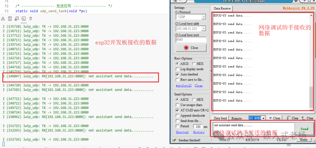
Data transmission between the ESP32 development board and the network debugging assistant:
Serial port return information:
I (929) main_task: Calling app_main()
�I (949) pp: pp rom version: e7ae62f
I (949) net80211: net80211 rom version: e7ae62f
I (951) wifi:wifi driver task: 3fcb69b0, prio:23, stack:6656, core=0
I (963) wifi:wifi firmware version: ccaebfa
I (963) wifi:wifi certification version: v7.0
I (963) wifi:config NVS flash: enabled
I (965) wifi:config nano formatting: disabled
I (969) wifi:Init data frame dynamic rx buffer num: 32
I (974) wifi:Init static rx mgmt buffer num: 5
I (978) wifi:Init management short buffer num: 32
I (983) wifi:Init static tx buffer num: 16
I (986) wifi:Init tx cache buffer num: 32
I (990) wifi:Init static tx FG buffer num: 2
I (994) wifi:Init static rx buffer size: 1600
I (998) wifi:Init static rx buffer num: 10
I (1002) wifi:Init dynamic rx buffer num: 32
I (1006) wifi_init: rx ba win: 6
I (1010) wifi_init: accept mbox: 6
I (1014) wifi_init: tcpip mbox: 32
I (1018) wifi_init: udp mbox: 6
I (1022) wifi_init: tcp mbox: 6
I (1025) wifi_init: tcp tx win: 5744
I (1030) wifi_init: tcp rx win: 5744
I (1034) wifi_init: tcp mss: 1440
I (1038) wifi_init: WiFi IRAM OP enabled
I (1043) wifi_init: WiFi RX IRAM OP enabled
I (1049) phy_init: phy_version 680,a6008b2,Jun 4 2024,16:41:10
W (1085) phy_init: saving new calibration data because of checksum failure, mode(0)
I (1121) wifi:mode : sta (d0:cf:13:15:23:38)
I (1121) wifi:enable tsf
I (1123) wifi:set country: cc=CN schan=1 nchan=13 policy=1
I (1124) main: Connecting to SSID:Xiaomi_AB83 …
I (1134) wifi:new:<11,0>, old:<1,0>, ap:<255,255>, sta:<11,0>, prof:6, snd_ch_cfg:0x0
I (1135) wifi:state: init -> auth (0xb0)
I (1195) wifi:state: auth -> assoc (0x0)
I (1229) wifi:state: assoc -> run (0x10)
I (1550) wifi:connected with Xiaomi_AB83, aid = 2, channel 11, BW20, bssid = 64:09:80:69:ab:84
I (1551) wifi:security: WPA2-PSK, phy: bgn, rssi: -38
I (1554) wifi:pm start, type: 1
I (1556) wifi:dp: 1, bi: 102400, li: 3, scale listen interval from 307200 us to 307200 us
I (1564) wifi:set rx beacon pti, rx_bcn_pti: 0, bcn_timeout: 25000, mt_pti: 0, mt_time: 10000
I (1572) wifi:AP’s beacon interval = 102400 us, DTIM period = 1
I (1579) main: Wi-Fi connected!
I (1581) wifi:
I (2579) esp_netif_handlers: sta ip: 192.168.31.101, mask: 255.255.255.0, gw: 192.168.31.1
I (2579) main: Got IP: 192.168.31.101
I (2582) main: Wi-Fi ready!
I (3585) lwip_udp: TX -> 192.168.31.223:8080
Key Information Explanation:
|
Serial Number |
Key Log |
Meaning |
|
1 |
main_task: Calling app_main() |
User program entry function starts execution |
|
2 |
wifi:mode : sta (d0:cf:13:15:23:38) |
Wi-Fi has switched to STA mode, MAC address as above |
|
3 |
main: Connecting to SSID:Xiaomi_AB83 … |
Starting to connect to the specified hotspot |
|
4 |
wifi:state: init -> auth -> assoc -> run |
Authentication → Association → Data path established, handshake process normal |
|
5 |
wifi:connected with Xiaomi_AB83 … rssi: -38 |
Successfully connected to AP, signal strength -38 dBm |
|
6 |
esp_netif_handlers: sta ip: 192.168.31.101 … |
DHCP completed,ESP32 obtained IPv4:192.168.31.101 |
|
7 |
main: Wi-Fi ready! |
Wi-Fi initialization process completed, business can start |
|
8 |
lwip_udp: TX -> 192.168.31.223:8080 |
UDP data has been sent to target IP:Port, sending path normal |
This article’s case uses the following software and hardware:
1. SOC Model: ESP32-S3-N16R8;
2. Software Development Environment: ESP-IDF 5.3.1, VSCode IDE (VSCodeUserSetup-x64-1.102.1 version);
3. ESP32 Project Version: IDF version (FreeRTOS);
4. Program Download: Type C USB (USB to Serial) interface;
5. This software and hardware case is for personal learning only and may not be used for commercial purposes.
References for this article:
“ESP32-S3 Technical Reference Manual Version 1.7”;
“ESP32-S3 Series Chip Technical Specification Version 2.0”.