Author | Didi Dada Dada
Editor | Autonomous Driving Technology Network
Original link:https://blog.csdn.net/m0_49384824/article/details/145343749
Click the card belowCard to follow the “Autonomous Driving Technology Network” public account
Technical content available
Introduction
The reasons for achieving high-precision time synchronization of multi-sensor data (Lidar, Camera, GPS/IMU) are as follows:
- 1. Each sensor has its own internal clock, and there is a “clock drift” between clocks, leading to inconsistent time references among sensors;
- 2. Different sensors have different sampling frequencies;
- 3. Data transmission, camera exposure, etc., can introduce uncontrollable delays.
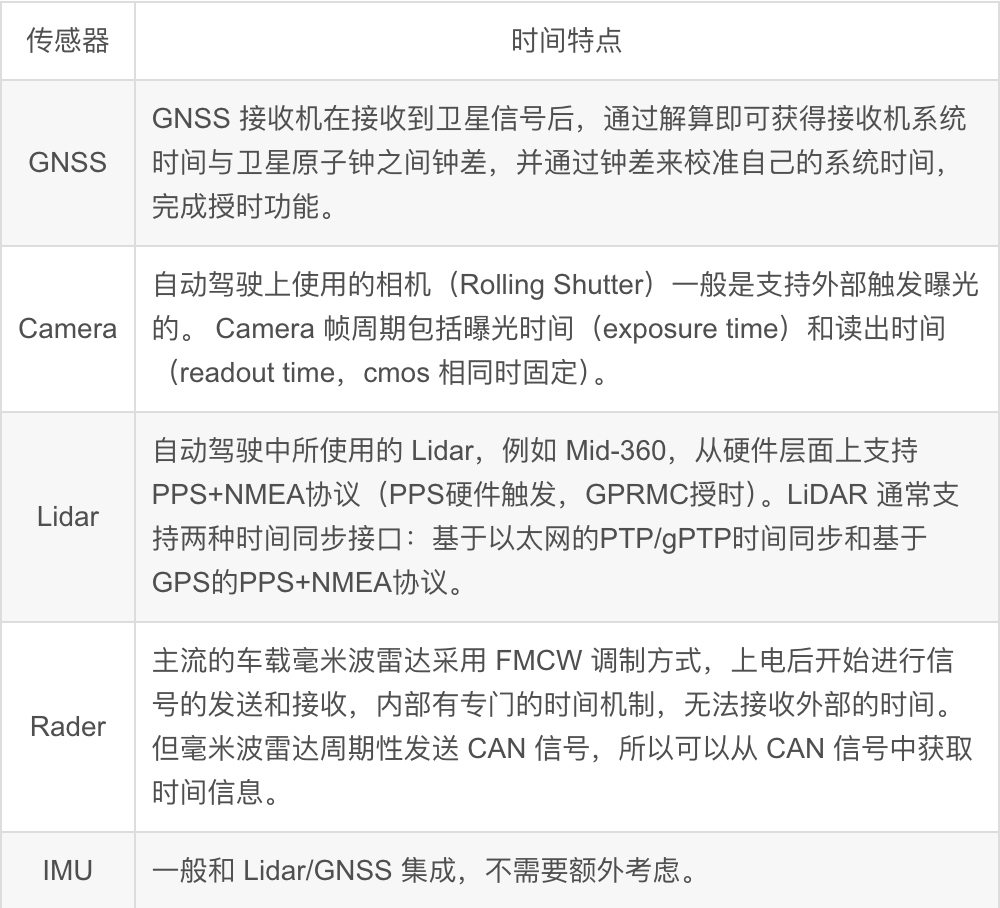
1. Characteristics of Multi-Sensor Time
2. Unified Clock Source
To solve the “clock drift” problem and provide a common time reference that all sensors follow, we introduce the concept of a unified clock source, as shown in the figure below: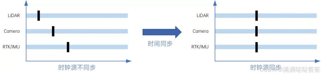
There are two common methods for unified clock sources: one is based on GPS with “PPS+NMEA” (Pulse Per Second + GPRMC), and the other is based on Ethernet using PTP (IEEE 1588) and gPTP (IEEE 802.1AS) clock synchronization protocols. The mainstream solution in the autonomous driving field combines these two methods, using GNSS clock time as the reference time and employing PTP/gPTP clock synchronization protocols to unify the clock sources among various sensors/domains, achieving time reference unification.
2.1 Clock Source
Currently, most autonomous driving systems are equipped with high-precision GNSS receivers, which have high-precision atomic clocks built into the navigation satellites. The GNSS receiver can calculate the time difference between its system time and the satellite atomic clock by decoding signals from at least four satellites, and calibrate its system time using this time difference to obtain ultra-high precision clock signals, which is the timekeeping function of GNSS.
Atomic clocks are currently the most accurate time-measuring instruments known to humanity. The movement of atoms between different energy levels is called “transition,” and when transitioning from a high energy level to a low energy level, electromagnetic waves are emitted. For the same type of atom, this frequency is fixed and is not affected by temperature and pressure, only related to its own energy, which is referred to in physics as the “resonance frequency.” Physicists obtain the accurate physical value of the resonance frequency through various physical means and use this value as the basic beat for generating time signals, which is the fundamental unit of measuring time. According to reports, the atomic clock on the BeiDou-3 satellite accumulates an error of only 1 second every 300 years.
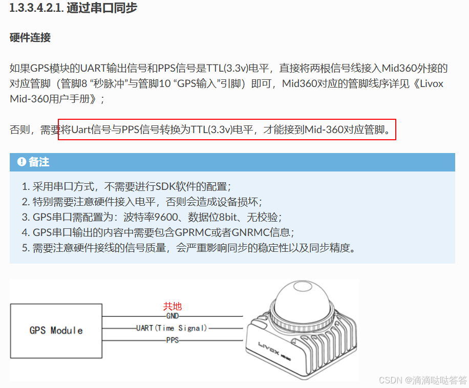
2.2 PPS+GPRMC
After the GNSS receiver acquires the clock signal, it outputs two types of synchronization signals: ① Synchronization pulse signal PPS, with a time period of 1 second and pulse width of 5ms to 100ms; ② GPRMC time synchronization message, output via a standard serial port, conforming to the GPRMC format, used to provide precise time synchronization information.
GPRMC is a standard format message that includes UTC time (accurate to the second) and latitude/longitude positioning data. Its format is as follows:
# Sample data$GPRMC,001155.00,A,2237.496474,N,11356.089515,E,0.0,225.5,230520,2.3,W,A*28
# Data descriptionfield 0: $GPRMC, format ID, indicating that this format is the recommended minimum specific GPS/TRANSIT data (RMC) recommended minimum positioning informationfield 1: UTC time, format hhmmss.ssss, representing hours, minutes, seconds, and millisecondsfield 2: Status A: indicates successful positioning V: indicates positioning failurefield 3: Latitude ddmm.mmmmmm degree format (if leading digits are insufficient, fill with 0)field 4: Latitude N (North) S (South)field 5: Longitude dddmm.mmmmmm degree format (if leading digits are insufficient, fill with 0)field 6: Longitude E (East) W (West)field 7: Speed (also 1.852 km/h)field 8: Course, degrees (2D direction, equivalent to a 2D compass)field 9: UTC date DDMMYY day, month, yearfield 10: Magnetic declination (000-180) degrees, if leading digits are insufficient, fill with 0)field 11: Magnetic declination direction E = East W = Westfield 12: Mode, A = automatic, D = differential, E = estimated, AND = invalid data (3.0 protocol content)field 13: Checksum
Here, the leading edge of the PPS pulse and the sending of the GPRMC message occur at the same time, with an error at the ns level, which can be ignored. The PPS second pulse (usually 1PPS, i.e., once per second) is a physical level output, and the time for receiving and processing the PPS signal is at the ns level, which can also be ignored. However, GPRMC data is generally sent via a serial port with a baud rate of 9600, and its sending, receiving, and processing time tx is at the ms level, which is the key to time synchronization. The following illustrates the principle of time synchronization using PPS+GPRMC.
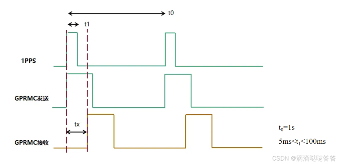
(1) After the device receives the PPS second pulse signal, it clears the milliseconds and below in its internal system time, which is based on the crystal oscillator as the clock source, and starts calculating the millisecond time from there.
(2) When the GPRMC data is received, extract the UTC time from the message, including year, month, day, hour, minute, and second.
(3) Add the time taken from receiving the second pulse to parsing the UTC time in the GPRMC to the UTC whole second time, synchronizing the system time. This completes one time synchronization. The same process is repeated every second for accurate calibration.
The limitations of achieving time synchronization for the entire autonomous driving system based solely on PPS and GPRMC:
PPS signal driving capability is insufficient: PPS is a low-power pulse signal, with a driving current range typically from 0.5mA to 20mA, making it difficult to trigger stable operation of multiple sensors.
PPS signal has weak anti-interference capability: The PPS signal is an unshielded single-wire pulse signal, which is easily interfered with in the complex electromagnetic environment of vehicles. When multiple PPS lines are laid inside the vehicle, it may be difficult to distinguish between interference pulses and valid synchronization pulses, leading to a decrease in signal accuracy.
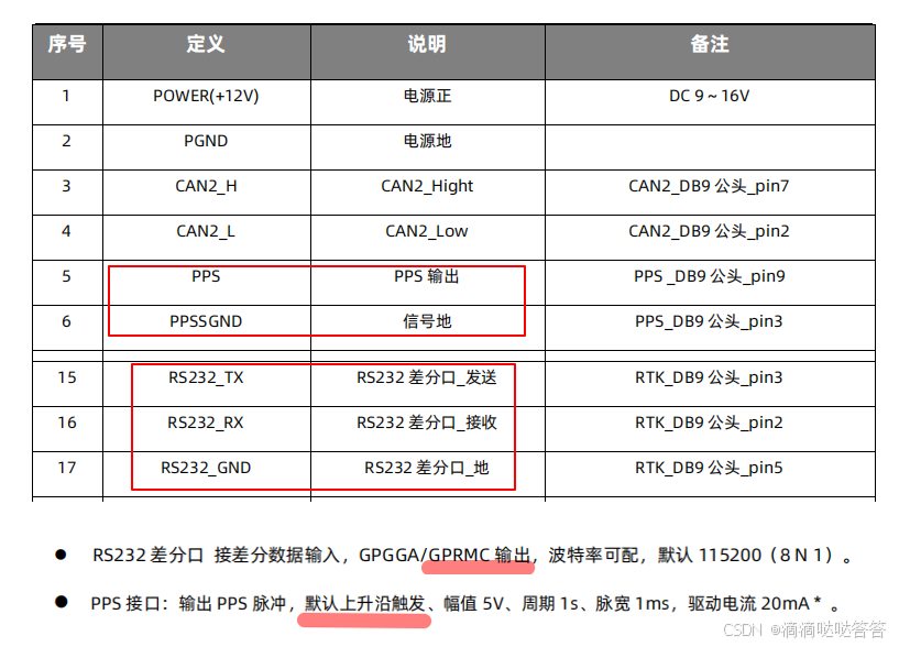
Transmission limitations of GPRMC messages: GPRMC messages are transmitted via RS232 serial ports, which are a 1-to-1 full-duplex communication form, allowing limited 1-to-N data transmission through a master-slave method. However, if synchronization transmission for dozens of devices is required, practical applications may face difficulties, requiring experimental verification of feasibility. Additionally, the complexity of wiring poses significant challenges for engineering design. The PPS+GPRMC information of the Duyuan INS570D vehicle-mounted combined navigation positioning system is as follows:
If connected to Mid-360, refer to:Mid-360 Time Synchronization Instructions
- Severe consequences of clock source failure: When the clock source is lost, all devices relying on synchronization will lose their unified reference, and each device’s clock will operate independently, losing global coordination. This situation is unacceptable in autonomous driving systems with high functional safety requirements, necessitating the design of redundancy mechanisms to ensure that a backup clock quickly takes over in the event of a primary clock failure, maintaining normal operation of the entire system.
2.3 PTP
PTP (Precision Time Protocol, IEEE 1588 V2) is a high-precision clock synchronization protocol based on Ethernet, which is a master-slave time synchronization system capable of achieving sub-microsecond clock synchronization between master nodes and slave nodes, provided that all nodes are interconnected via Ethernet, switches support the PTP protocol, and each node supports the PTP protocol.
The network ports running the PTP protocol in devices are called PTP ports, with the PTP master port used to release time and the PTP slave port used to receive time. Three types of clock nodes are defined: Boundary Clock (BC), Ordinary Clock (OC), and Transparent Clock (TC).
(1) Boundary clock nodes have multiple PTP ports, one of which is used to synchronize time with upstream devices, while the other ports are used to send time to downstream devices. When the upstream time synchronization device of the boundary clock node is a GNSS receiver, the boundary clock node becomes a master clock node (optimal clock).
(2) Ordinary clock nodes have only one PTP port, used to synchronize time with upstream clock nodes.
(3) Transparent clock nodes have multiple PTP ports, forwarding the received time without protocol parsing, and do not participate in time synchronization internally.
PTP synchronizes by exchanging synchronization messages between master and slave devices and recording the message sending time to calculate network transmission delays and clock offsets between master and slave devices. PTP defines four synchronization messages: Sync, Follow_Up, Delay_Req, and Delay_Resp, with the precise synchronization process as follows:
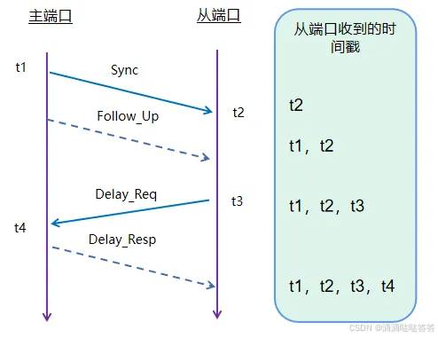
(1) The PTP master port sends a Sync message to the slave port, synchronously recording the time t1 when the Sync is sent. After the slave port receives the Sync message, it records the time t2 when it was received.
(2) The master port then sends the time t1 in a Follow_Up message to the slave port. After the slave port receives this message, it can parse t1 and derive the first equation: t1 + T_delay (network delay) + T_offset (clock offset) = t2.
(3) The slave port sends a Delay_Req message to the master port, synchronously recording the time t3 when the Delay_Req is sent. The master port records the time t4 when it receives the message.
(4) The master port then sends the time t4 in a Delay_Resp message to the slave port. After the slave port receives this message, it can parse t4 and derive the second equation: t3 + T_delay (network delay) – T_offset (clock offset) = t4.
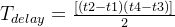
Assuming that the network delay is symmetric, meaning that the upstream and downstream delays are equal, solving the equations yields:
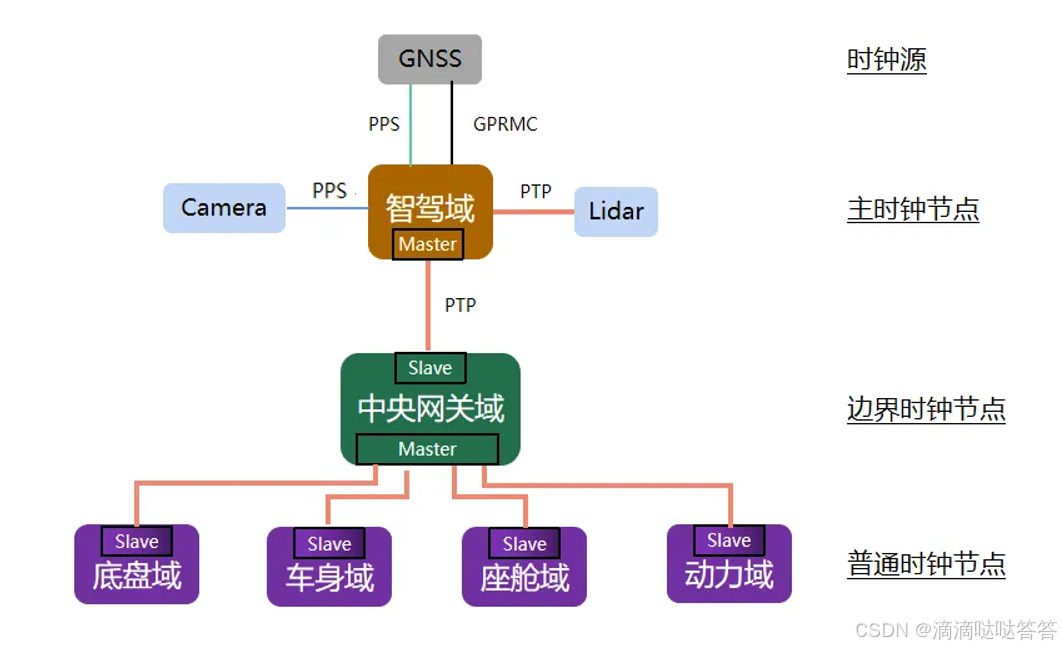
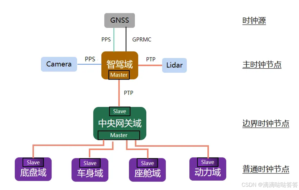
2.4 Global Architecture Time Synchronization Scheme
In a global architecture, the intelligent driving domain controller is directly connected to the GNSS receiver (or built-in), and since GNSS is an excellent clock source, the intelligent driving domain controller naturally becomes the master clock node. The central gateway domain controller connects other domain controllers through the vehicle’s Ethernet backbone, making it the best choice for boundary clock. Thus, when the clock source is lost, the boundary clock node synchronizes the system time of the master clock node, maintaining relative time consistency within the entire global architecture.
For other domain sensors and actuators that require time synchronization, if not needed, this domain controller can be designed as an ordinary clock node. If needed, it can be designed as a boundary clock to ensure relative time unification in the absence of a clock source.
The time synchronization scheme for Ethernet-based devices is already well-established, while for non-vehicle Ethernet devices with strong synchronization needs, cameras need special handling. The camera can be set to external trigger mode, receiving external trigger pulse signals from the main control, i.e., PPS. When the camera takes a photo, the exposure moment will also generate a pulse signal sent to the main control, which records the system time at that moment and embeds the timestamp data into the camera’s image data.
3. Timestamp Errors
After unifying the clock source, each sensor’s data has a globally consistent time reference. However, a new problem arises: different sensors have different sampling frequencies, such as Lidar (typically 10Hz) and cameras (typically 30Hz). This leads to delays in obtaining synchronized data at specific times, which can cause significant errors in dynamic environments.
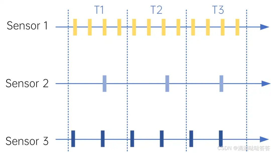
As shown in the figure below, three sensors have different sampling frequencies. At time T1, sensor 2 has a data point, and we need to find the corresponding data for sensors 1 and 3. The method of searching is to find the data packet from the corresponding sensor that is closest in time to the timestamp of sensor 2. If the time difference between the searched data packet and the timestamp of sensor 2 at T1 is large, combined with the fact that both the vehicle and obstacles are moving, the error can be significant. To mitigate the timestamp search error, the main methods used are hardware synchronization and software synchronization.
3.1 Hardware Synchronization
Hardware synchronization is a method to ensure the consistency of data collection times among different sensors through physical signals. A common hardware synchronization method is to use the PPS signal as a trigger. The PPS signal is an accurate clock signal that can trigger sensors to collect data at specific time points, thereby changing the data collection frequency of the sensors. In addition to serving as a unified clock source, the GNSS system can also utilize its PPS pulse to trigger sensors to collect data at specific time points. When using the PPS pulse from GNSS, the timestamp in the data packet provided by the sensor is aligned to the absolute time (GPS timestamp) rather than the sensor’s timestamp. Since the frequency of GNSS’s PPS is typically only 1Hz, a device is usually needed to forward the PPS signal to any frequency (frequency division, 1Hz -> 10Hz), but with the same phase as the original PPS signal, allowing control of the data collection frequency of each sensor.
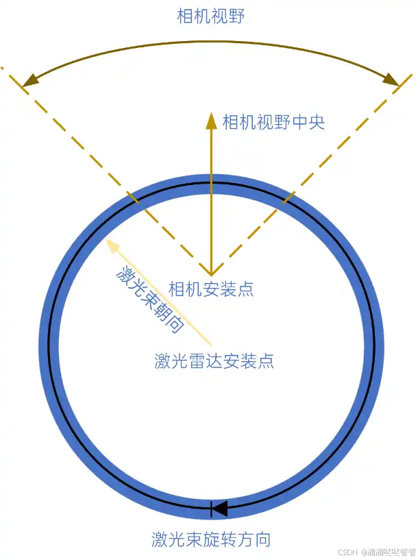
For example, Lidar and cameras can be configured to collect data on the rising edge of the PPS signal, ensuring that their data collection is synchronized. Specifically, the Lidar can use its phase-locking function to synchronize with the PPS signal, as shown in the figure below. By aligning the phase-locking angle of the Lidar with the center of the camera’s field of view, the camera can be triggered when the Lidar’s laser beam rotates to the centerline of the camera’s field of view, achieving synchronized collection.
Of course, since Lidar continuously rotates to collect data while the camera exposes instantaneously, hardware synchronization can only achieve an approximation. For example, if the frame rate of the Lidar is 10Hz, the time difference between the earliest and latest points collected in one frame of point cloud may reach 100ms. The camera, due to its instantaneous exposure, collects all pixel points at the same time. Therefore, for the point cloud at the center of the camera’s field of view, the collection time is consistent with the image capture time, but for point clouds at the edges of the field of view, there is a certain time deviation, which may range from 5ms to 20ms.
3.2 Software Synchronization
Software synchronization is a method for time correction of sensor data during the data processing phase. When hardware synchronization cannot be achieved or is insufficient to meet system requirements, software synchronization provides a solution by using known timestamps and sensor motion information to infer the accurate time points of sensor data.
The interpolation and extrapolation method is a commonly used algorithm in software synchronization. Synchronization is achieved through the following steps:
Time difference calculation: First, calculate the time difference between two sensor data frames. For example, if there is a Lidar data frame and a camera data frame, their timestamps may differ, and we need to find the difference between these two timestamps.
Motion information acquisition: Collect the motion information of the sensors during the two timestamp periods, which usually includes speed, acceleration, and rotation.
Position inference: Using the motion information of the sensors and the time difference, infer the target’s position change between the two time points using physical models or machine learning models.
New frame creation: Based on the inferred target position, create a new data frame that represents the state at a certain time point between the two original data frames.
Software synchronization compensates for the shortcomings of hardware synchronization through intelligent data processing techniques, improving the synchronization accuracy of sensor data. However, it also requires additional computation and real-time requirements, necessitating careful design and optimization of algorithms to achieve efficient and accurate synchronization.
3.2.3 Other Methods
① message_filters package in ROS
ROS provides the message_filters package for time soft synchronization. message_filters acts like a message buffer, subscribing to different sensors’ topics. When messages arrive at the message filter, they are not immediately output but are output under certain conditions, producing a synchronization result that is then processed in the callback function.
message_filters only outputs data from different sensors that are close in the timeline and does not actively synchronize! For more details, refer to ROS Time Synchronization – Using message_filters for Time Soft Synchronization.
② Double-ended queue std::deque
Using a double-ended queue std::deque to store data from different sensors, judging based on the timestamps of different sensor data, and processing data that meets the time synchronization requirements. Similar to the message_filters package, it only outputs data from different sensors that are close in the timeline.
std::queue buf1;std::queue buf2;std::thread process;//typedef M sensor data type, e.g., sensor_msg::PointCloud2, sensor_msg::Image, etc.void callback1(M& msg){// Data enqueue buf1.push(msg);// Other code...}void callback2(M& msg){// Data enqueue buf2.push(msg);// Other code...}void process_comparation(){while(ros::ok()){ M data1=buf1.front(); M data2=buf2.front();if(data1.header.timestamp.toSec()>data2.header.timestamp.toSec()){ buf2.pop(); }else buf1.pop();// Other operations on data1 and data2}}int main(int argc,char** argv){// Initialization}Click the card belowCard to follow the “Autonomous Driving Technology Network” public account
Technical content available