Introduction:
With the rapid development of automotive intelligence, ADAS (Advanced Driver Assistance Systems) is gradually being applied to heavy-duty truck models. The currently achievable functions include: Lane Departure Warning (LDW), Forward Collision Warning (FCW), Automatic Emergency Braking (AEB), Adaptive Cruise Control (ACC), and more.
As technology advances, people’s demands for the safety and comfort of vehicles are increasing. The A-pillar is the connecting pillar between the windshield and the front door, which not only bears the weight of the roof but also ensures that the passenger’s survival space is not compressed during impacts or rollovers [1].
01
Components of the ADAS System
The ADAS system consists of three parts: sensors (input signals), controllers, and actuators (output signals). The sensors include a front monocular camera and millimeter-wave radar; the execution system consists of the engine and the EBS electronic braking system. The composition of the ADAS system is shown in Figure 1.
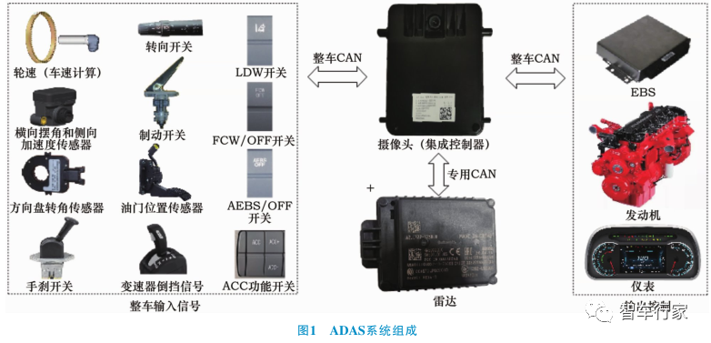
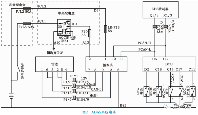
The circuit of the ADAS system is shown in Figure 2. There is a dedicated CAN line communication between the radar and the camera to achieve data fusion. The controller built into the camera communicates with the EBS, engine ECU, BCU, dashboard, and other electronic control units via PCAN.
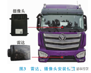
The installation positions of the radar and camera are shown in Figure 3.
1) Millimeter-Wave Radar
The front millimeter-wave radar of the ADAS system is installed inside the front bumper of the vehicle. Since millimeter waves are reflected by metal, the distance and relative speed of the target vehicle ahead can be calculated based on the time it takes for the radar to receive the reflection from the vehicle in front. The advantage of radar lies in measuring longitudinal distance. The national standard requires that the effective testing distance of the radar be no less than 150m.
2) Monocular Camera
The camera, installed in the middle of the lower inner side of the windshield, is used to identify lane lines, vehicles, and pedestrian targets. The advantage of the camera lies in detecting lateral angles and positional relationships. The system realizes the lane departure warning function based on the camera signal; while functions such as FCW, AEB, and ACC require the fusion of radar and camera signals.
02
Functions of the ADAS System
2.1 Lane Departure Warning Function
Lane lines can be identified (white or yellow solid and dashed lines that meet national standards), and when the vehicle speed is within the range of 60~110km/h, if the vehicle unintentionally departs from its lane, a lane departure alarm will be triggered (the dashboard warning light flashes while the buzzer sounds). The LDW system also has requirements for lane conditions. When the vehicle is traveling on sharp curves (with a turning radius of less than 250m) and narrow (lane width less than 2.5m) sections, the lane departure warning will not work.
If the vehicle departs from its lane but the driver actively controls the vehicle, the system will not alarm. Such actions include: turning on the turn signal, sudden steering, braking, pulling the handbrake, etc.
2.2 Automatic Emergency Braking
The system determines the most relevant target to the vehicle (i.e., the vehicle ahead with the same trajectory, traveling in the same direction, and at the closest distance) through data fusion, while vehicles in adjacent lanes are ignored. The AEBS system works at speed ranges of 15~110km/h. Figure 4 shows a schematic diagram of the vehicle locking the associated target.When a collision danger is detected, the AEBS system intervenes.The intervention process is divided into three stages: warning, partial braking, and full braking.The three levels of response for the AEBS system are shown in Figure 5.
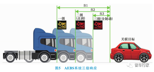
1) Warning Stage:The driver is alerted to take control of the vehicle through the flashing yellow warning light and the buzzer sound (first-level alarm). If the driver does not take control of the vehicle, it enters the partial braking intervention.
2) Partial Braking Stage:The system sends a braking command to the EBS system while issuing a second-level alarm (flashing red warning light and buzzer sound). If the vehicle is still not taken over during this stage, it will trigger full braking.
3) Full Braking Stage:The system sends a full braking command to the EBS system while issuing a third-level alarm (flashing red warning light and high-frequency buzzer sound).
The AEBS system can reduce the speed before a collision, mitigating impact, but it cannot completely avoid a collision, especially when the target is stationary or crossing vehicles. When the AEB function is activated, the system sends a torque limit command to the engine ECU via the vehicle’s CAN network. The targets applicable for the AEBS function include buses, trucks, passenger cars, motorcycles, bicycles, and pedestrians.
The following actions by the driver are recognized as active takeover, and the system exits intervention:① The rate and amount of steering wheel rotation exceed certain thresholds; ② The increase in throttle pedal travel and the rate of pressing exceed certain thresholds; ③ The throttle pedal exceeds the forced downshift threshold (85%) for a certain time; ④ The position and time of the brake pedal exceed certain thresholds; ⑤ The turn signal and time exceed certain thresholds; ⑥ Operating the AEBS switch.
The AEBS function is disabled under the following conditions:① Speed is too slow (14.4km/h) or too fast (126km/h); ② The relative speed between the vehicle and the target is too slow; ③ The vehicle is reversing; ④ EBS system failure; ⑤ ESP function abnormal; ⑥ Radar or camera failure.
2.3 Adaptive Cruise Control
The Adaptive Cruise Control (ACC) system locks onto the target vehicle traveling in the same trajectory ahead by fusing monocular camera and radar data, and then controls the throttle and braking to follow the target vehicle at a set time distance. When there are no vehicles ahead, the system automatically switches to fixed-speed cruise mode.
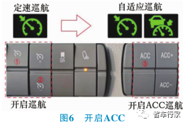
1) ACC Cruise Operation:When the vehicle speed reaches the desired speed, press the cruise switch to enter fixed-speed cruise mode. After enabling fixed-speed cruise, pressing the ACC switch (Figure 6) will activate adaptive cruise mode.
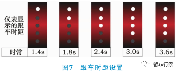
2) Following Control Function:The vehicle follows the preceding vehicle at the time distance set by the driver. The driver can adjust the following time distance using the ACC+ and ACC- switches. The following distance settings are shown in Figure 7.
3) Fixed-Speed Control: The driver sets the target cruise speed through the cruise switch, with a speed range of 30-100km/h. When there are no target vehicles ahead or the speed of the target vehicle exceeds the target cruise speed, the system operates in fixed-speed control mode, maintaining a constant speed through engine torque control.
4) Applicable Targets: ACC responds to the rear-end scenarios of passenger cars, trucks, buses, etc. (excluding vehicles traveling in the opposite direction and crossing vehicles); for special vehicles such as bicycles, motorcycles, electric vehicles, and tricycles, they can only be selected as target vehicles when traveling at high speed.
There are two conditions for ACC release.
Immediate Release Conditions: ① Press the brake pedal; ② Pull the handbrake; ③ Speed exceeds 110km/h; ④ AEB function activated; ⑤ Driver turns off cruise; ⑥ ACC-related system failure.
Soft Release Conditions: ① Engine off; ② Gear lever not in forward gear; ③ ABS activated; ④ ASR activated; ⑤ ESC (ESP) activated; ⑥ Speed below 25km/h; ⑦ ACC main control switch off; ⑧ Fixed-speed cruise enters shutdown state.
Conclusion
The ADAS system perceives the surrounding environment of the vehicle, collects and processes analytical data, can provide early warnings to the driver, and effectively intervene in emergencies, significantly increasing the comfort and safety of driving. The ADAS system is a prerequisite for exploring the realization of autonomous driving in the future. Currently, the primary operation of ADAS is still the driver himself, who must remain in a driving state to take over the vehicle at any time. In the future, the main subject of autonomous driving will be the system, which will have stricter requirements based on multi-sensor fusion and deep learning for both technology and vehicle performance.