Here we introduce thetouch screen and PLC connection considerations. The article may be a bit complex, but with careful reading, it can be understood.
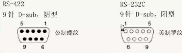
Interface Types
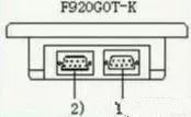
(1) Connect to the PLC port (RS-422) 9-pin D-sub, female. It can connect to the PLC via RS-422, or connect two or more GOT modules (except for F920GOT-K) through this port. (2) Connect to the personal computer/PLC port (RS-232C) 9-pin D-sub, male. This port is used to create screen data using design software. It can also connect to the PLC or microcomputer motherboard (only Q series PLC can connect in F920GOT-K): it can also connect two or more GOT modules (via RS232C), barcode readers, or printers (except for F920GOT-K).
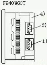
(3) PLC port (RS-232C) 9-pin D-sub, male. Connect to the PLC or microcomputer motherboard; it can also connect two or more GOT modules (via RS-232C), barcode readers, or printers. (4) Personal computer port (RS-232C) 9-pin D-sub, male. Used to connect to the personal computer to create screen data using design software, or connect to barcode readers or printers. This port cannot be used to connect to PLC.
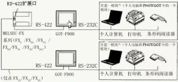
Connecting F900GOT with Peripheral Devices 1) FX Series PLC 1) Directly connect CPU (RS 422)
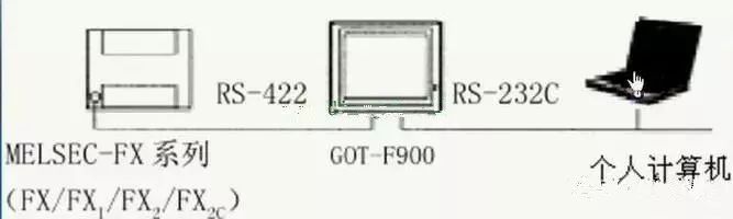
■ If connected through an optional RS-422 communication board, an additional programming port can be added, allowing each port to connect to one GOT or personal computer (to establish ladder diagram programs or screen design software, except for F920GOT-K).
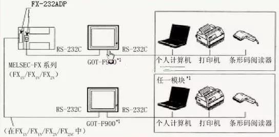
(2) Directly connect CPU (RS-232C) ■ By adding an RS-232C communication board, an additional programming port can be added, allowing each port to connect to one GOT or personal computer (ladder diagram programs or screen design software), (only when the GOT is equipped with two RS 232 channels can it connect to a personal computer, printer, or barcode reader, except for F920GOT-K).
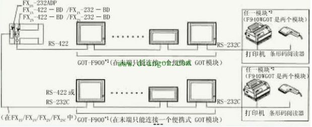
(3) Connection of two or more GOT modules (except for F920GOT-K). At least four GOT modules can be connected to the programming port of FX series PLC (FX0/FX0S/FX1S/FX0N/FX1 N/FX2N/FX2NC) or optional communication port (FX1S/FX1N/FX2N/FX2NC).
(4) Directly connect CPU (RS-422).
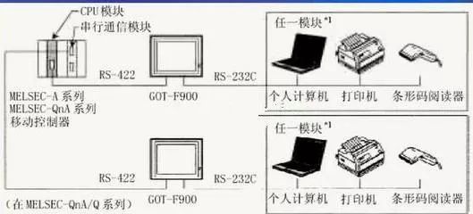
F900GOT (except for F920GOT-K) connects to the programming port of Q/QnA series PLC or motion controller module interface. When the personal computer connects to F900GOT, programming can be done directly. As shown in Figure 2-10. When the serial communication module is connected to the CPU module, F900GOT can only connect to one of the two interfaces, and connecting two F900GOT to one communication module is not allowed.
(4) Connection of two or more GOT modules.
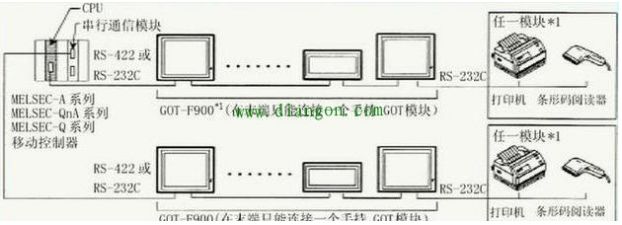
In A/QnA series PLC, up to four F900GOT (except for F920GOT-K) modules can be connected to the PLC’s programming interface or serial communication module interface. As shown in Figure 2-12. For the serial communication module, F900GOT can only connect to one of them and cannot occupy two interfaces simultaneously.
(5) F900GOT connected to FX positioning modules (10GM/20GM)
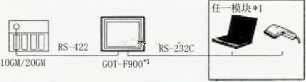
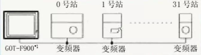
F900GOT (except for F920GOT-K) can be directly connected to the programming port (RS—422) of FX positioning modules (10GM/20GM). Through the RS232C interface of GOT, it can connect to personal computers, printers, or barcode readers. F900GOT (except for F920GOT-K) is connected to FREQROL series inverters: F900GOT (except for F920GOT-K) is connected to the built-in PU port of FREQROL series inverters. One F900GOT can connect to a maximum of 10 inverters.
The pin arrangement of the communication interface. The pin arrangement of the built-in serial interface of F930GOT/F930GOT-K/F940GOT/F940WGOT is shown in the figure: