

There is a certain XX machine, driven by a 7.5kW motor. Depending on the raw materials, the speed needs to be infinitely adjustable within a certain range, and the system must protect itself in case of excessive raw materials or equipment jamming. The machine is equipped with cooling water, which must not exceed 50℃, and the cooling water pipes must not be blocked or run dry, as blockage and lack of water can lead to serious consequences. The cooling water’s power is not on this equipment, and the water temperature and pressure must be displayed.

① Analyze the Problem.
Based on the known process requirements, the analysis conclusions are as follows.
a.The main motor’s speed is required to be adjustable, so an inverter should be selected.
b.The system requires timely protection in case of equipment jamming. When the load exceeds a certain value (especially when the motor jams), the current rises sharply. When the current reaches a certain value, it can be determined that the motor is jammed, and the motor’s current can be measured.
Since an inverter is used, the inverter can measure the motor’s instantaneous current, and this instantaneous current value can be obtained via communication.
c.Clearly, this system needs a controller. PLC and microcontroller systems are options, but the development cycle for a microcontroller system is long, and developing a single unit is not cost-effective. Therefore, PLC control is chosen. Since this system is not complex, a small PLC can meet the requirements.
d.Cooling water blockage and lack of water can be judged by pressure. When the water pressure exceeds a certain value, it is considered that the cooling water is blocked; when the pressure is below a certain value, it is considered that there is a lack of water. Pressure is generally measured using a pressure sensor, and temperature is measured using a temperature sensor. Therefore, the PLC system needs to be configured with an analog module.
e.The water temperature and pressure need to be displayed, so a touch screen or other device is required for display.
② Hardware System Integration.
a.Hardware Selection.
• Small PLCs can be used as alternatives. Since the Siemens S7-200 SMART series PLC has strong communication capabilities and a good cost-performance ratio, it is preliminarily determined to choose the S7-200 SMART series PLC. Because the PLC needs to communicate with the inverter, it will occupy one communication port, and communicating with the touch screen will also occupy one communication port. The CPU SR20 has a programming port (PN) for downloading programs and communicating with the touch screen, while another serial port can be used for USS communication.
Since the signals from the pressure transmitter and temperature transmitter are current signals, it is necessary to consider using a dedicated AD module. Using EMAI4 for two signals is an appropriate choice. Since the I/O points of CPU SR20 are suitable, the CPU SR20 is chosen.
• MM440 is a powerful inverter with a moderate price, which can easily communicate with S7-200 SMART via USS, so the MM440 inverter is chosen. The touch screen is chosen as Siemens Smart 700 IE.
b.System Hardware and Software Configuration.
• 1 CPU SR20.
• 1 EMAI4.
• 1 Smart 700IE touch screen.
• 1 MM440 inverter.
• 1 pressure sensor (including transmitter).
• 1 temperature sensor (including transmitter).
• 1 set of STEP7-MicroWin SMART V1.0.
• 1 set of WINCC FLEXIBLE 2008 SP4.
c.Schematic Diagram. The system schematic diagram is shown in Figure 4-1.

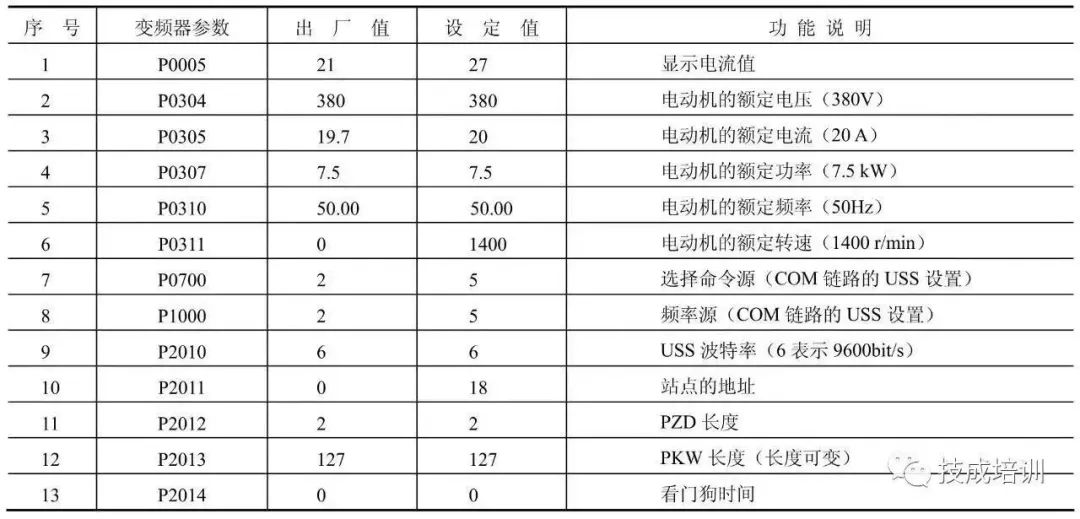
d.Inverter Parameter Settings. The inverter parameter settings are shown in Table 4-2.

① I/O Distribution.The PLC I/O distribution is shown in Table 4-3.

② Write Program.
The maximum measurement range of the temperature sensor is 100℃, and its corresponding digital value is 27648, so the digital value collected by AIW16 divided by 27648 and multiplied by 100 (i.e., ) is the temperature value; the maximum range of the pressure sensor is 10000Pa, and its corresponding digital value is 27648, so the digital value collected by AIW18 divided by 27648 and multiplied by 10000 (i.e., ) is the pressure value; VD0 in the program is the percentage of rated frequency. Since the rated speed of the motor is 1400r/min, assuming the motor speed is 700r/min, then VD0=50.0, so VD0=VD50÷1400×100. The program is shown in Figure 4-5.


This example uses the Siemens Smart 700IE touch screen, which has a high cost-performance ratio, and its usage is similar to other Siemens touch screen series. The following describes the process of creating its project.
① First, create a new project, then establish a new connection, as shown in Figure 4-47. Select the “SIMATIC S7 Smart” communication driver, and set the communication interface between the touch screen and PLC to “Ethernet”, setting the PLC’s IP address to “192.168.0.1” and the touch screen’s IP address to “192.168.0.2”, this step is crucial.

② Create Variables.Variables are the medium for data exchange between the touch screen and PLC. Create variables as shown in Figure 4-6.

③ Configure Alarms.Double-click on “Analog Alarms” in the project tree to display the configuration alarm interface as shown in Figure 4-7.

④ Create Screens.This example has three screens, as shown in Figures 4-50 to 4-52.
⑤ Animation Connection.In each screen, connect the configured variables with the screen.
⑥ Save, Download and Run the Project, the running effect is shown in Figures 4-50 to 4-52.


Disclaimer: This article is reproduced from the internet, and the copyright belongs to the original author. If there are any copyright issues, please contact us for deletion. Thank you!
Complete Question Bank for 2023 Electrician Junior Exam (including answers)
3 Essential Tools for Electricians, Easily Accessible via WeChat!
[Collect] The “Path” of a Veteran Electrician, Secrets to Earning Over 10,000 a Month!
Which of the Five Major Electrical Drawing Software (CAD, Eplan, CADe_simu…) Do You Choose?
Latest Electrical CAD Drawing Software, with Detailed Installation Tutorial!
Latest Electrical Drawing Software EPLAN, with Detailed Installation Tutorial!
Common Issues for Beginners Using S7-200 SMART Programming Software (with Download Link)
Comprehensive Electrical Calculation EXCEL Sheets, Automatically Generated! No Need to Ask for Help!
Bluetooth Headsets, Books for Electricians/PLC Entry, Free Gifts Await You!
Basic Skills in PLC Programming: Ladder Diagrams and Control Circuits (includes 1164 practical cases for Mitsubishi PLC)
Still Can’t Understand Electrical Diagrams? Take Away Basics of Electrical Diagram Recognition and Simulation Software, Quickly Get Started!
12 Free Electrician Video Courses, 10GB Software/E-books, 30 Days of Free Live Electrician Courses Available!
