We are learning about programming continuous control programs. Before writing the program, the first step is to create a project, add devices, and save the project.

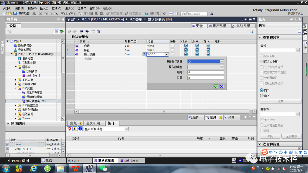
Next, open the “Default Variable Table” under “PLC Variables” in the project tree on the right.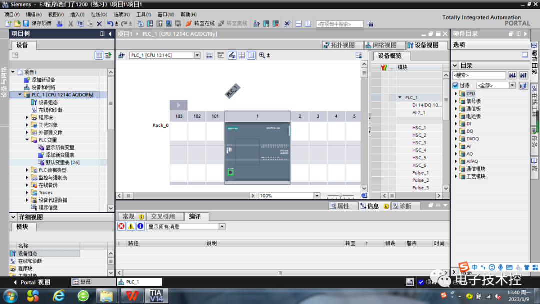
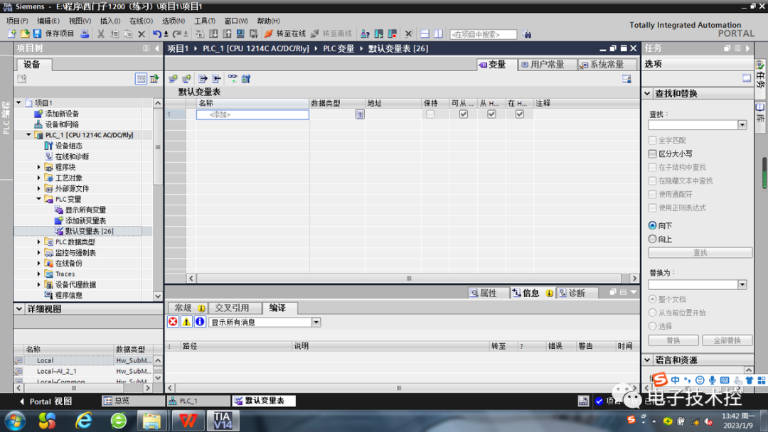 In the default variable table, we add variables, which means we add comments to addresses like I0.0. In fact, we can also add comments during the ladder diagram programming process, but when we program in SCL language later, we can only add comments in the variable table. We should start developing this habit now.When adding variables, the default data type is “bool”. A boolean value is a digital value, which can be either “0” or “1”. In addition to the boolean type, the Siemens S7-1200 PLC has many other data types, which can be seen in the table below.
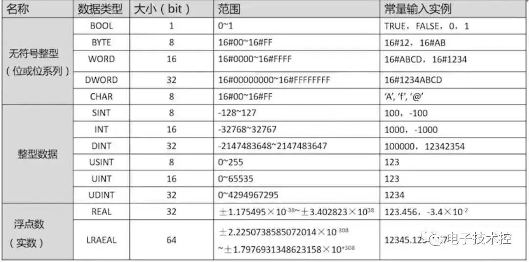 In the software, we can see about 50 different data types, and the above are some commonly used data types. Today, we will only use “bool”; we will learn about other data types as we use them.When editing the variable table, we can edit the data type and address in the dropdown menu on the right, or we can directly input modifications in the fields to change them to our desired data types and addresses.
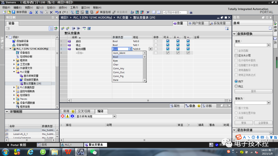
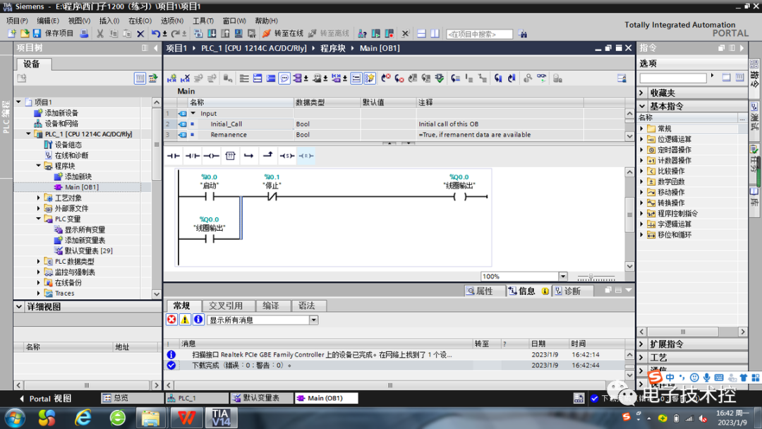
 After setting, we can open Main[OB1] in the project tree under “Program Blocks” to start programming.
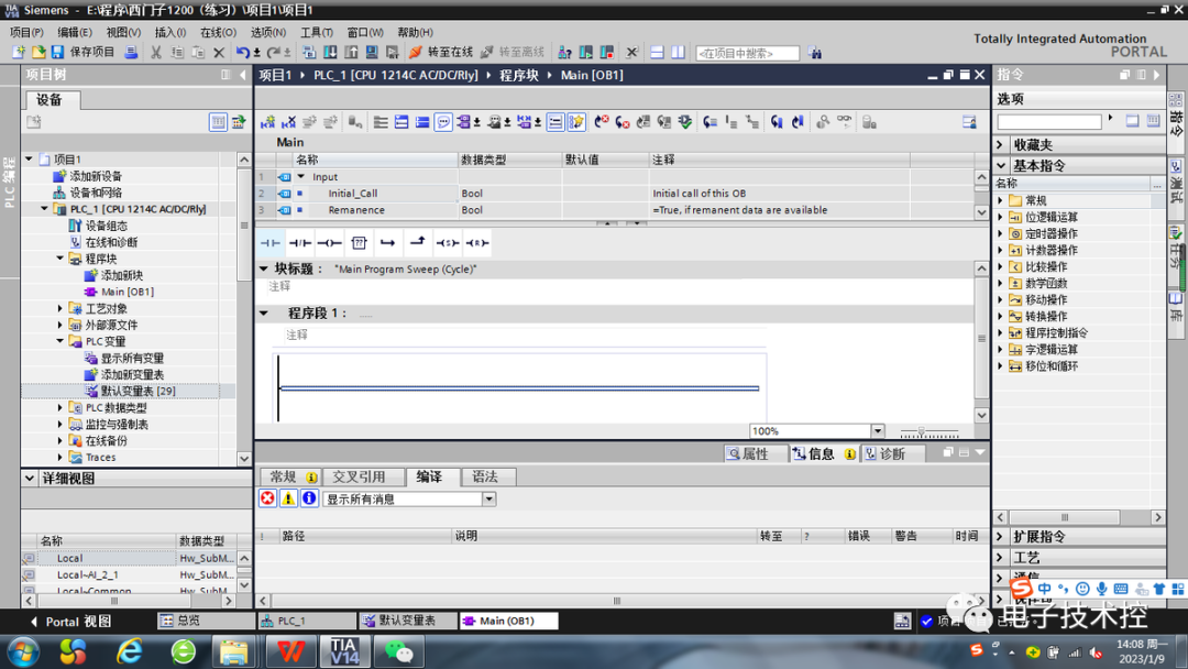 When writing the program, we can directly drag from the red box (favorites bar) into the program segment, or we can find it in the basic instructions for “Bit Logic Operations” on the right. From left to right, the items are normally open contacts, normally closed contacts, coils, empty function blocks, open branches, nested closures, and set/reset instructions. We can also modify the convenient buttons in the favorites bar according to our habits.
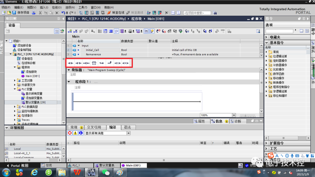 After dragging, double-click the question mark above and enter the address.
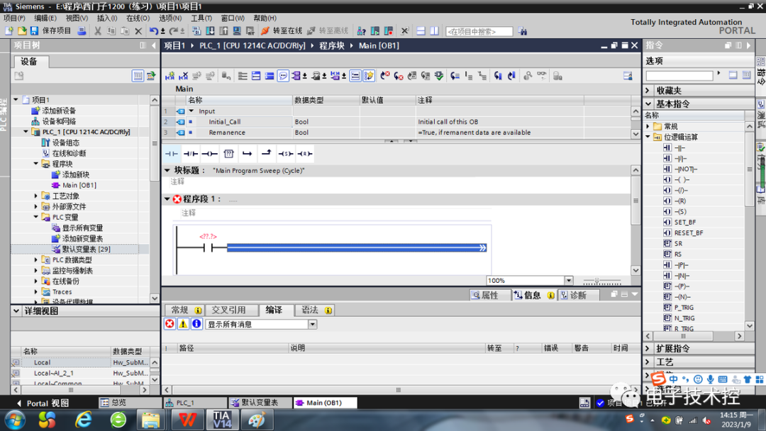 If parallel connections are needed, use the “Open Branch” and “Nested Closure” buttons in the red box to achieve this.Since we have already edited the variable table, when we input the address during programming, the corresponding comments will automatically display. After completing the program, we can compile and download it to the PLC.
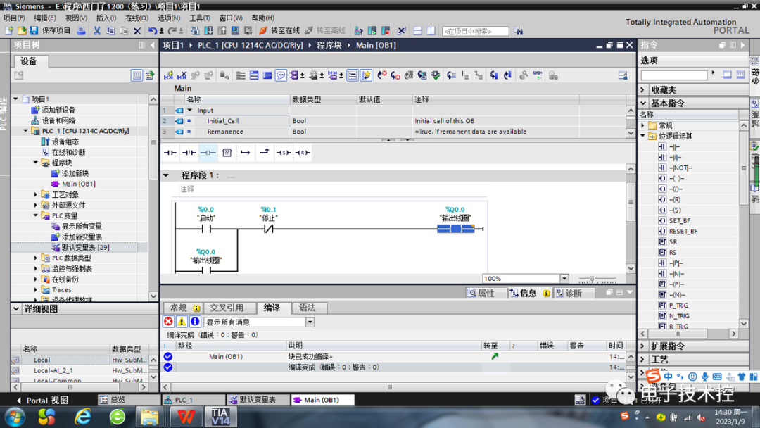 When the program is connected, the normally open contact I0.0 is activated, and the output coil Q0.0 operates. The self-locking contact of output coil Q0.0 closes to maintain its operation. When the normally closed contact I0.1 is disconnected, the output coil Q0.0 stops working, and the self-locking contact of output coil Q0.0 opens.