
Click the blue text
Follow us
Abstract:
What exactly are the differences between CAN FD and traditional CAN? How do they differ in terms of data transmission and real-time performance?
With the rapid development of automotive electronics and industrial automation, the number of devices and data volume on the CAN bus has greatly increased, posing significant challenges to the CAN bus. To meet the demands for higher bandwidth and data throughput, CAN FD (CAN with Flexible Data-Rate) was born. So what exactly are the differences between CAN FD and traditional CAN? How do they differ in terms of data transmission and real-time performance?
Basic Concepts:
CAN FD (Controller Area Network with Flexible Data-Rate) is a communication protocol that is an improvement over the traditional CAN (Controller Area Network) protocol. Compared to CAN, CAN FD has a higher bandwidth and transmission rate, allowing for more data transmission. It also supports more frame formats to meet different data transmission needs.
There are generally three reasons for transitioning from traditional CAN to CAN FD:
01 CAN FD increases bit rate while providing shorter CAN frames
– Shorter latency.
– Better real-time performance.
– Higher bandwidth.
02 CAN FD can accommodate more data from 8 to 64 bytes within a CAN frame
– Relatively less system overhead = better data throughput.
– Simpler and more efficient software when sending larger data objects.
03 CAN FD features a higher performance CRC algorithm
– Reduces the risk of undetected errors.
Since CAN FD is a product of the increasing data load on the CAN bus reaching its limits, this article aims to compare CAN FD with traditional CAN while providing a detailed introduction to CAN FD.
01. Data Frame Format of CAN FD vs. Traditional CAN
Figure 1 compares the traditional CAN frame (top) and the CAN FD frame (bottom). Both frames are single-byte data, and in this example, the CAN FD frame does not increase the bit rate. It can be seen that both frames are the same from the Start of Frame (SOF) bit to the entire 11 arbitration bits. After arbitration, the traditional CAN (marked as A) has a Remote Transmission Request bit (RTR bit), while the CAN FD frame has a Remote Request Replacement bit (RRS bit). For data frames, this bit is always dominant (0) in both frame formats. The dominant bit, typically defined as logical 0 and 0 volts signal, is represented by a thicker black line at the bottom (marked as B).
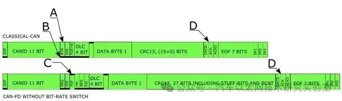
Figure 1 Comparison of Traditional CAN and CAN FD Frames
The bit following the Remote Transmission Request bit (RTR bit) is the Identifier Extension bit (IDE bit), indicating that the frame uses the 11-bit arbitration basic frame format. Note that this article will not cover the Extended Frame Format (EFEFF) using 29-bit arbitration.
After the IDE bit is the r0 bit (reserved bit), which is always dominant in the traditional CAN frame format. In the CAN FD frame format, this bit is recessive (see C), indicating that the frame is not a traditional CAN frame but a reserved format CAN frame, now referred to as CAN FD (CAN Flexible Data-rate). In other words, this bit indicates whether the CAN frame is a traditional CAN frame or a CAN FD frame. Since the release of the ISO11898-1 standard, this bit has been referred to as the FDF bit (Flexible Data Format bit), replacing the name r0 bit used in previous versions of the ISO11898-1 standard. Any reference to the r0 bit in previous documents or datasheets is the same as the FDF bit in the ISO11898-1 version released in 2015.
02. Additional Bits in CAN FD
The FDF bit/r0 bit (from now on referred to as the FDF bit) is followed by the reserved bit (res) for the FD format and the Data Length Code bit (DLC) for the traditional CAN format. In other words, all traditional CAN controllers generated according to the previous ISO11898-1 standard will incorrectly interpret CAN FD frames, leading to erroneous frames from traditional CAN controllers. After the Cyclic Redundancy Check (CRC) delimiter (marked as D in Figure 1), traditional CAN and CAN FD are consistent in their bit patterns. In other words, before the next frame begins, both traditional format and FD format use the same end pattern.
All CAN FD controllers can handle a mix of traditional CAN frames and CAN FD frames. This means that it is feasible to start using CAN FD controllers in existing systems that only use traditional CAN format. When all older traditional CAN controllers are replaced with CAN FD controllers, traditional CAN frames can be mixed with CAN FD frames or only one type can be used.
After the FDF bit in the CAN FD frame is the reserved bit. Setting this bit to recessive indicates future protocols, similar to how the FDF bit indicates the transition from traditional CAN to CAN FD format. Future protocols have not yet been defined. It is worth noting that the r0/FDF bit in the traditional CAN format was used to indicate that the CAN FD format took 25 years to develop.
After the reserved bit is the BRS bit (Bit Rate Switch). This additional bit allows CAN FD frames to be sent in two different formats. If the BRS bit is sent as dominant, all bits will be sent at the same bit rate used in the arbitration shown in Figure 1. If the BRS bit is recessive, the frame format following this bit will use a higher bit rate until and including the CRC delimiter.
The BRS bit is followed by the ESI bit (Error State Indicator), which is usually sent as dominant by the master. If the sending node of the CAN FD frame becomes error-passive, this bit will be sent as recessive, indicating that the sending node has significant communication issues. It is currently unclear how this bit will be used in broader applications, but it has already been adopted by automotive manufacturers as needed.
After these three new bits (reserved bit, BRS bit, and ESI bit) are four DLC bits, indicating the number of data bytes in the CAN frame. Table 1 shows how these four bits are used to indicate the number of data bytes in the CAN frame. Traditional CAN frames can accommodate up to 8 bytes of data. As can be seen from the table, exceeding 8 bytes can send a DLC code, but only 8 bytes of data will be placed in the transmitted CAN frame. A close look at the table reveals that DLCs from 9 to 15 differ in the CAN FD format. Any number of bytes from 9 to 63 requires 6 bits of DLC, and up to 64 bytes will require 7 bits of DLC. The compromise is to maintain 4 bits of DLC and limit the byte length in CAN FD frames (12, 16, 20, 24, 38, 48, and 64).
03. CAN FD Significantly Increases Data Transmission Rate
The data after the DLC bit (Figure 1 shows a CAN frame with one data byte). The bits before and after this data are a fixed length of any number of data bytes. In this example, to transmit one byte of data, the traditional format requires 55 bits, while the CAN FD format requires 70 bits. In the worst case, multiple padding bits can also be included in the frame. If the frame exceeds 5 bits in the same level line, the protocol will add an extra bit with inverted polarity to ensure that level changes can be used to resynchronize the sampling point.
This addition and removal of extra bits for resynchronization is called padding, and these bits are marked as padding bits in the CAN protocol. By packing more data into each CAN frame, data transmission efficiency is improved, as can be seen from the last two columns of Table 1. The efficiency equation assumes the worst-case number of padding bits in the overhead. Due to its lower overhead, traditional CAN is slightly more efficient compared to CAN FD. By increasing the number of bytes in the CAN FD frame from 8 bytes to 64 bytes, efficiency can increase from 50% to 88%.
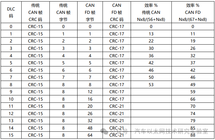
The table also includes the CRC codes used with different frame formats. The traditional CAN format uses a 15-bit CRC encoding for all frame types, as all frames have similar lengths. The CAN FD frame is a bit more complex because a 64-byte frame is 8 times longer than an 8-byte frame. To address this, two different CRC lengths are used in CAN FD frames: if the frame is 16 bytes or less, a 17-bit CRC-17 is used; and if the CAN frame is 20 bytes or more, a 21-bit CRC-21 is used.
It is the 2 extra bits of CRC plus 4 bits in the padding counter and fixed padding bits that make the CAN FD frame longer than the traditional CAN frame. Some may argue that this comparison is not entirely fair, as traditional CAN frames can have up to 3 padding bits in the CRC segment and 3 bits in the control segment.
The extra bits in the CRC segment of the CAN FD frame provide better protection for the data content, and high system security is a sufficient reason to transition from traditional CAN to CAN FD.
When there are more than 8 bytes of data in the CAN frame, the increased efficiency will lead to increased data throughput, which is another reason for transitioning from traditional CAN to CAN FD.
04. Balancing Data Transmission Efficiency and Real-Time Performance
It is important to remember that while the efficiency of using longer CAN frames has indeed improved, the number of CAN frames and frames per second has decreased, which increases latency in communication and reduces real-time performance. To mitigate this issue and increase data throughput, the possibility of increasing the bit rate in CAN FD frames above that of traditional CAN can be utilized.
So far, the description of CAN FD has been with the same bit rate throughout the entire CAN frame. As mentioned above, the recessive BRS bit will require switching to a higher bit rate in the data portion of the frame.
In Figure 2, a third CAN frame has been added. This third frame is a CAN FD frame with the same content as the intermediate CAN FD frame, but in this case, the frame is sent at twice the data rate of the intermediate CAN FD frame.
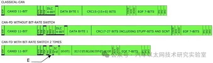
Figure 2 CAN FD Frame Without/With Increased Data Rate by 2 Times
Since it has the same content, you will get the same DLC and data, but when CAN FD is sent at a higher bit rate, the BRS bit will be sent recessive (see E). The BRS bit is included in the CRC calculation, which will generate two different CRC contents even if the CAN-ID, DLC, and data are the same.
From Figure 2, it can be seen that the first bit sent at a higher bit rate is the ESI bit, followed by the DLC, data bytes, and CRC bits. The last bit sent at a higher bit rate is the CRC delimiter. Thus, it can be understood that the higher bit rate applies not only to the data segment of the CAN FD frame but also to the surrounding bits.
Figure 3 is the same as Figure 2, except for a new frame below the previously described frame. This new frame has the same content as all other frames, but the bit rate is eight times the arbitration bit rate. The variation is relatively large compared to CAN FD frames with constant bit rates or double bit rates.
It can be seen that not only does the single byte of data achieve a higher bit rate, but the DLC and CRC parts of the frame also do, totaling about 40 bits.
Figure 4 shows three CAN frames, with the top being an 8-byte traditional CAN frame. The middle is a CAN FD frame with 64 bytes, and the bottom CAN frame is the same CAN FD frame content, but with an increased bit rate (speed increased eight times).
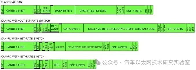
Figure 3 A CAN FD Frame with an 8 Times Increased Bit Rate Based on Figure 2
From Figure 4, it can be seen that more data will make the CAN frame transmission time longer, which will prevent other high-priority CAN frames from starting to send. To maintain real-time performance, it is necessary to increase the bit rate to reduce the length of CAN frames and minimize the time CAN frames occupy the communication line, thus preventing other high-priority frames from accessing the communication.

Figure 4 Top is an 8-byte Traditional CAN Frame;
The middle is a 64-byte CAN FD Frame with the same bit rate;
The bottom is a 64-byte CAN FD Frame with an 8 Times Increased Bit Rate
In summary, CAN FD with a high bit rate will increase real-time performance, as the higher bit rate reduces the transmission time of CAN frames, thereby decreasing latency in communication. By transmitting more data in each frame, data throughput can be increased, but if not combined with a higher bit rate, this will reduce real-time performance. In many cases, 64-byte long CAN frames are used in programming, which is usually done when the system is paused and no real-time control is running. Even without real-time demands, using a higher bit rate to improve data throughput is still beneficial and shortens download times.




Source:
*Disclaimer: This article is original or forwarded by the author. If it inadvertently infringes on someone’s intellectual property, please inform us for deletion.The above images and text are sourced from the internet. If there is any infringement, please contact us in a timely manner, and we will delete it within 24 hours.The content of the article reflects the author’s personal views,and the Automotive Ethernet Technology Research Laboratory reprints it only to convey a different perspective, not representingthe Automotive Ethernet Technology Research Laboratory’s endorsement or support of this view. If there are any objections, please feel free to contact the Automotive Ethernet Technology Research Laboratory.
Original link:
https://blog.csdn.net/yessunday/article/details/131722201