
Click the blue text
Follow us
Abstract:
Why is it necessary to install terminal resistors in CAN bus networks?
In the article detailing the characteristics of CAN bus: high-speed CAN bus and low-speed CAN bus, it is stated that both high-speed and low-speed CAN networks require terminal resistors to be installed.
High-speed CAN networks require terminal resistors to be added to CAN_H and CAN_L, and the terminal resistors on the cable should match the nominal impedance of the cable, which is generally 120Ω. Each terminal resistor should be able to dissipate 0.25W of power (standard source: ISO 11898-2:2003).
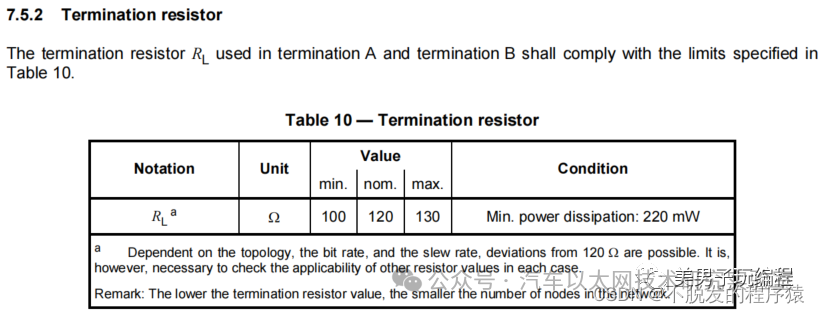
The value of terminal resistors in low-speed CAN networks is not fixed. Philips recommends that for low-speed CAN networks, the overall RTH and RTL terminal resistors should be between 100Ω and 500Ω (each). The total network terminal resistance can be determined using the following formula:

Why is it necessary to install terminal resistors in CAN bus networks? There are three main reasons:
-
Improve anti-interference capability, allowing high-frequency low-energy signals to dissipate quickly;
-
Ensure the bus quickly enters a recessive state, allowing the energy of parasitic capacitance to dissipate faster;
-
Improve signal quality by placing resistors at both ends of the bus to reduce reflected energy.
Improve anti-interference capability
The signals on the CAN bus distinguish between two states: “dominant” and “recessive”. The “dominant” state corresponds to binary “logic 0”, while the “recessive” state corresponds to binary “logic 1”. The determination of “dominant” or “recessive” is made by the CAN transceiver. The following diagram shows the internal logic block diagram of a CAN transceiver:
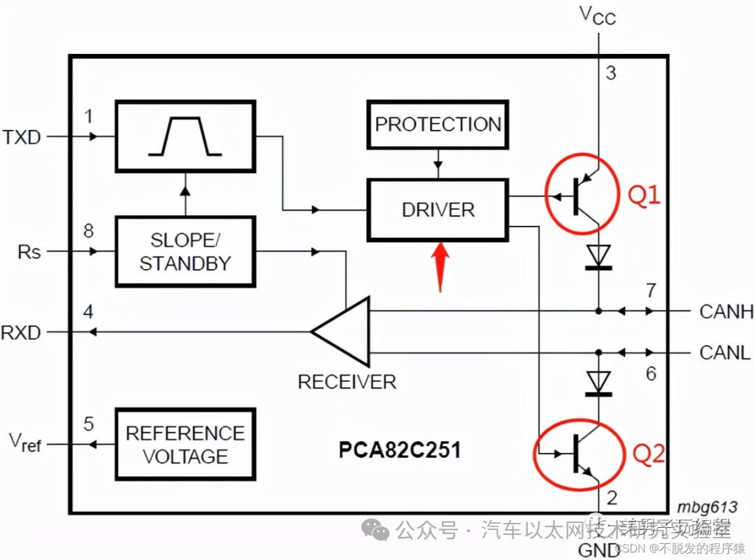
When the bus is in the “dominant” state, the internal Q1 and Q2 of the transceiver are conducting, creating a voltage difference between CANH and CANL; when in the “recessive” state, Q1 and Q2 are off, and CANH and CANL are in a passive state with a voltage difference of 0.
When the bus is loaded, in the “recessive” state, the differential resistance is very high, and external interference requires only a small amount of energy to switch the bus to “dominant” (the minimum voltage threshold for a typical transceiver to determine “dominant” is only 500mV; when the voltage difference is 500mV, the bus is judged to be “dominant”). When there is differential mode interference on the bus, there will be noticeable fluctuations, and these fluctuations have no place to be absorbed, creating a dominant bit on the bus.
Therefore, to enhance the anti-interference capability of the bus in the recessive state, a differential load resistor can be added, with a resistance value as small as possible to eliminate most noise energy. However, to avoid requiring excessive current for the bus to enter the “dominant” state, the resistance value cannot be too small.
Ensure the bus quickly enters the recessive state
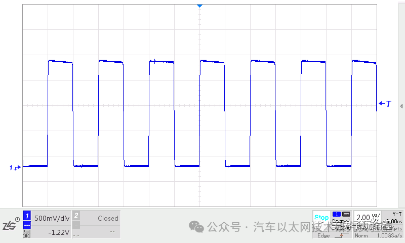
Due to the unavoidable presence of parasitic capacitance on the bus, during CAN bus data transmission, the transitions between “recessive” and “dominant” states will charge and discharge the parasitic capacitance. If there is no resistive load on the bus, the signal waveform will exhibit a “slow change” process. As shown in the following diagram:
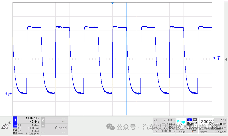
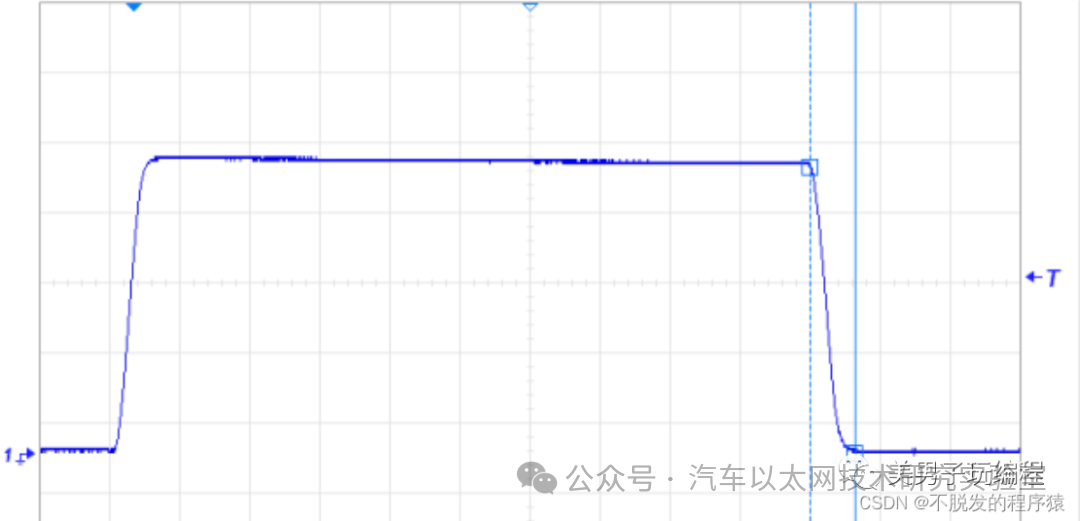
Upon enlarging the above diagram, it can be seen that the time taken for the dominant state to revert to the recessive state is as long as 1.44μS. Under high sampling points, communication can barely be maintained; if the communication rate is higher or the parasitic capacitance is larger, it becomes difficult to ensure normal communication. As shown in the following diagram:
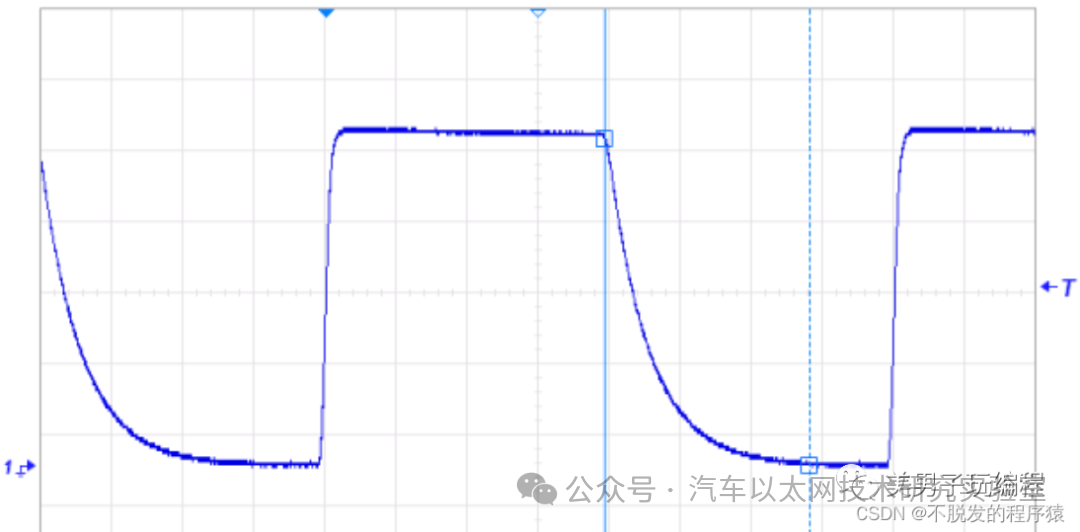
To allow the parasitic capacitance of the bus to discharge quickly and ensure the bus quickly enters the recessive state, a load resistor should be placed between CANH and CANL.
After adding a 60Ω resistor, it can be seen from the above diagram that the time taken for the dominant state to revert to the recessive state is reduced to 128nS, which is comparable to the time taken to establish the dominant state.
From the waveform comparison above, it can be observed that terminal resistors enable the bus to change states between “dominant” and “recessive” more quickly.
Absorb reflected signals to improve signal quality
At high transition rates, when signals encounter impedance changes, signal reflections occur; changes in the geometric structure of the transmission line cable will also cause changes in the characteristic impedance, leading to reflections. Reflected signals can return and affect quality, causing “ringing” on the bus, as shown in the following diagram:
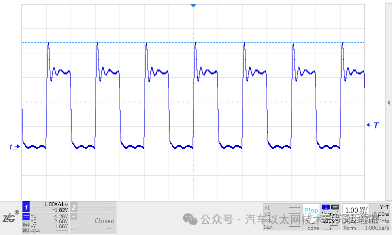
If the “ringing” signal is too large, it will affect signal quality and may even cause errors in bus data transmission.
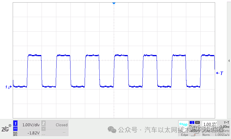
By adding a terminal resistor at the end of the cable that matches the cable’s characteristic impedance, the energy of the reflected signals can be absorbed, preventing ringing, as shown in the following diagram:




*Disclaimer: This article is original or forwarded by the author.If any party’s intellectual property rights are inadvertently infringed, please inform us for deletion.The above images and text are sourced from the internet; if there is any infringement, please contact us in a timely manner, and we will delete it within 24 hours.The content of the article represents the author’s personal views,and the Automotive Ethernet Technology Research Laboratory reprints it only to convey a different perspective, not representingthe Automotive Ethernet Technology Research Laboratory’s endorsement or support of this view. If there are any objections, please contact the Automotive Ethernet Technology Research Laboratory.
Original link:
https://blog.csdn.net/yessunday/article/details/130327017