In the field of industrial control, time is a core dimension that runs through the entire production process—from timestamping device operation logs to timed production scheduling, and to accurately tracing the moment of faults, all of which rely on the PLC’s precise control of real-time. The S7-1200 PLC, as the core device of Siemens’ small and medium-sized automation systems, has local real-time (Local Real Time) read and write functions that are fundamental for time-related control. This article will guide you step by step from configuration to programming, mastering the methods for reading and writing local time on the S7-1200 PLC.
1. Core Understanding: Real Time and DTL Data Type of S7-1200
Similar to clocks in daily life, the S7-1200 PLC has a built-in real-time clock module that can operate independently and maintain the current date and time, even during power outages (when equipped with a supercapacitor or battery module). To achieve time reading and writing, it is essential to clarify the storage format of time data in the PLC—DTL Data Type.
DTL (Date and Time Long) is a long date and time type with an operand length of 12 bytes, capable of fully storing information such as year, month, day, hour, minute, second, millisecond, and day of the week. It is the standard format for processing time data in the S7-1200 PLC. Subsequent read and write operations essentially revolve around data interaction with DTL type variables.
2. Preliminary Preparation: TIA Portal Configuration and Data Block Creation
Reading and writing time on the S7-1200 PLC requires first completing device configuration and data block setup in TIA Portal software, laying the groundwork for program writing, which can be divided into two steps:
2.1 Device Addition and Basic Configuration
Step 1: Open TIA Portal software, create a new project and name it (e.g., “S7-1200_Time_Operation”), in the project view under “Devices and Networks”, click “Add New Device”, select the corresponding model of S7-1200 PLC (this article uses CPU 1214C DC/DC/DC as an example), after adding the device, the system will automatically generate the OB1 main program block.
Step 2: Create a dedicated data block for time, right-click on “Program Blocks” → “Add New Block”, select “Data Block”, name it “TIME_DB”, with the storage type defaulting to “Global Data Block”, and click OK to complete the creation.
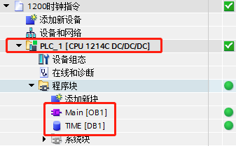
Figure 1: Device Addition and Data Block Creation Interface
(This is the location of the image mentioned in the original text for the first step of configuration, showing the process of device addition and TIME DB block creation)
2.2 DTL Type Variable Definition
Open the “TIME_DB” data block, create a new variable in the variable table, the name can be customized (e.g., “Local_Time”), select the data type as “Date and Time” (i.e., DTL type), and no initial value needs to be filled (it will be assigned later through the program reading real-time). After defining, save the data block, ensuring there are no syntax errors.
The 12 bytes of the DTL type variable correspond to different time dimensions, for example, bytes 0-1 store the year (UInt type), byte 2 stores the month (USInt type), byte 3 stores the day (USInt type), and subsequent bytes correspond to hour, minute, second, millisecond, etc. This structured storage facilitates the separate invocation of specific time dimensions later.

Figure 2: DTL Time Data Type Definition Interface
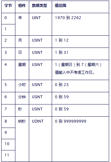
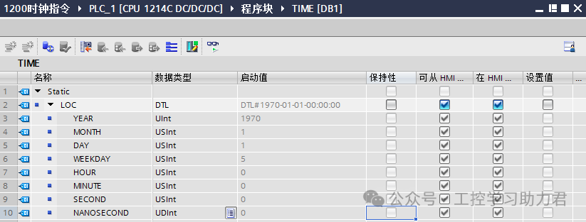
(This is the location of the image mentioned in the original text for creating the DTL type, showing the association settings of variable names and DTL types)
3. Reading Local Time: Application of RD_LOC_T Instruction
To read the local real-time of the S7-1200 PLC, the dedicated instructionRD_LOC_T (Read Local Time) must be called, which can read the current time from the PLC’s built-in clock into a specified DTL type variable. The specific operation is divided into four steps:
3.1 Calling the RD_LOC_T Instruction
Open the LAD (Ladder Diagram) editing interface of the OB1 main program, find the “RD_LOC_T” instruction in the instruction list under “Extended Instructions” → “Time and Date”, and drag it into the programming area. This instruction has only two pins: “RET_VAL” (return value, 16-bit integer type) and “OUT” (output, DTL type).
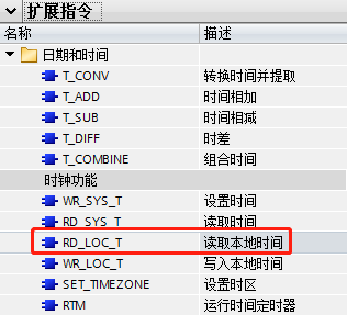
Figure 3: RD_LOC_T Instruction Calling Interface
(This is the location of the image mentioned in the original text for the first step of reading time, showing the position of the instruction in the TIA Portal instruction list and how to call it)
3.2 Instruction Parameter Association
Assign parameter values to the pins of the RD_LOC_T instruction:
-
RET_VAL Pin: Connect a 16-bit integer type variable (which can be defined in the temporary variable table of OB1, such as “Error_Code”), used to feedback the execution status of the instruction—if the value is “0”, it indicates that the instruction executed successfully; if it is a non-zero value, it corresponds to different error codes (the meanings of which can be found in the Siemens official manual).
-
OUT Pin: Connect the DTL type variable defined earlier in TIME_DB (e.g., “TIME_DB.Local_Time”), this pin is used to store the read local real-time.
To avoid frequent refreshing of time data consuming system resources, it is recommended to use a “conditional read” method, such as triggering the instruction execution by the rising edge of a button signal (e.g., I0.0), or setting it to execute periodically (e.g., reading once every second). If real-time updates are needed, the instruction can be placed directly in the unconditional network of OB1 (suitable for scenarios requiring high time accuracy).
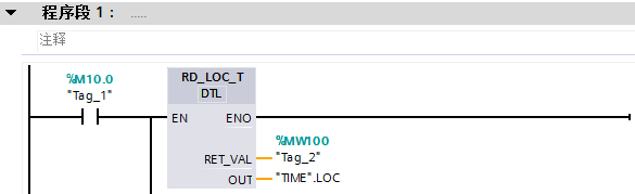
Figure 4: Conditional Read Time Program Writing Interface
(This is the location of the image mentioned in the original text for conditional reading, showing the logic of the button signal and RD_LOC_T instruction linkage)
3.3 Program Download and Time Reading Demonstration
Download the completed OB1 program and TIME_DB data block to the S7-1200 PLC, ensuring the PLC is in “Run” mode. After triggering the reading condition (e.g., pressing the button corresponding to I0.0), open the “Online and Diagnostics” mode, and monitor the value of the “Local_Time” variable in the TIME_DB data block, where you can see the real-time updated date and time, for example, “DTL#2025-11-19-15:30:22.123”, indicating the current time is November 19, 2025, 15:30:22.123.
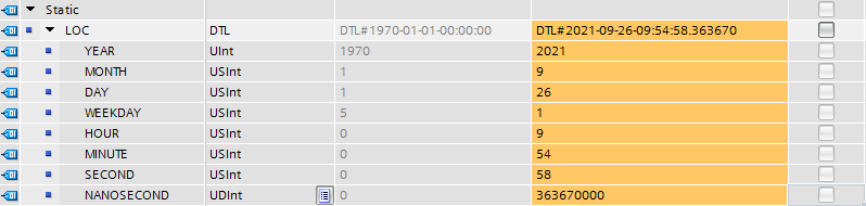
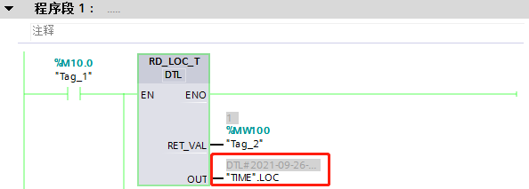
Figure 5: Local Time Reading Demonstration Interface
(This is the location of the image mentioned in the original text for the time reading demonstration, showing the real-time value of the DTL variable during online monitoring)
3.4 Separate Reading of Time Dimensions
If only a specific dimension of time (e.g., the current hour) needs to be read, there is no need to call additional instructions; simply use “TIME_DB.Local_Time.Hour” to obtain it (“Hour” is a built-in property of the DTL type). For example, writing the instruction “L #TIME_DB.Local_Time.Hour” in the program can load the current hour into the accumulator for subsequent timing control logic (e.g., automatic shutdown at 18:00).
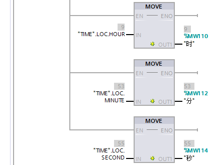
Figure 6: Separate Time Dimension Reading Interface
(This is the location of the image mentioned in the original text for sequentially reading time, showing how to call individual dimensions such as hour and minute through variable properties)
4. Writing Local Time: Application of WR_LOC_T Instruction
When the local time of the S7-1200 PLC is inaccurate (e.g., after initial power-up or time disorder after a power outage), it is necessary to write a new time using theWR_LOC_T (Write Local Time) instruction, which updates the specified DTL type time value to the PLC’s built-in clock. The operation requires attention to the specificity of the trigger method, with the specific steps as follows:
4.1 Calling the WR_LOC_T Instruction
In the OB1 main program, drag the “WR_LOC_T” instruction from the instruction list under “Time and Date” into the programming area. This instruction has three pins: “RET_VAL” (return value, 16-bit integer), “LOCTIME” (input, DTL type), and “EN” (enable, boolean type).
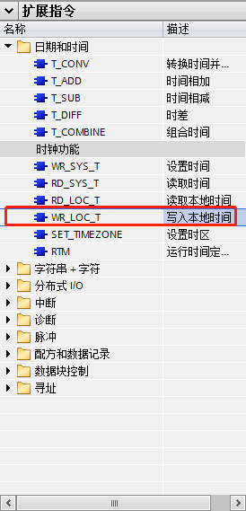
Figure 7: WR_LOC_T Instruction Calling Interface
(This is the location of the image mentioned in the original text for the first step of writing time, showing how to call the WR_LOC_T instruction)
4.2 Parameter Configuration and Trigger Logic
The parameter configuration and trigger logic of the WR_LOC_T instruction require special attention to the format of “LOCTIME” and the trigger method of “EN”:
-
LOCTIME Pin: Fill in the target time, the format must be “DTL#year-month-day-hour:minute:second”, for example, “DTL#2026-12-14-14:00:00” (the millisecond part can be omitted, defaulting to 0). This value can be directly filled in as a constant or assigned through a DTL type variable (suitable for scenarios where time needs to be dynamically modified).
-
EN Pin and Trigger Logic: This is the key to writing time—the WR_LOC_T instruction can only be activated once; if the EN pin remains continuously activated, the CPU will keep executing the write operation, but the time will not change (the PLC’s built-in clock only accepts a single update instruction). Therefore, it must be triggered by a rising edge, for example, connecting a button signal (I0.1) through a “P” (rising edge detection) instruction to the EN pin, ensuring that the write operation is triggered only once when the button is pressed.
-
RET_VAL Pin: Also connect a 16-bit integer variable (e.g., “Write_Error”), where 0 indicates a successful write, and a non-zero value indicates a write failure (common reasons include incorrect time format, PLC being in stop mode, etc.).
-
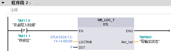
Figure 8: Writing Time Program Writing Interface
(This is the location of the image mentioned in the original text for the rising edge trigger writing, showing the logic of I0.1, rising edge instruction, and WR_LOC_T linkage)
4.3 Writing Effect Verification
After downloading the program, press the button corresponding to I0.1 to trigger the write operation, then read the local time using the RD_LOC_T instruction, or check the current time in TIA Portal under “Online and Diagnostics” → “Device Status” → “Real-Time Clock”. If it displays the set time of “2026-12-14-14:00:00”, it indicates that the write was successful.
If the write fails, check three key points first: 1) whether the LOCTIME time format complies with the “DTL#year-month-day-hour:minute:second” specification (e.g., month cannot exceed 12, date cannot exceed the maximum days of the month); 2) whether the EN pin is triggered by a rising edge (to avoid continuous activation); 3) whether the PLC is in “Run” mode (writing to the real-time clock is not possible in stop mode).
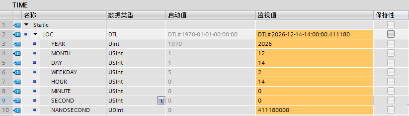
Figure 9: Time Writing and Reading Verification Interface
(This is the location of the image mentioned in the original text for the writing effect demonstration, showing the comparison of time changes before and after writing)
5. Practical Application Scenarios and Precautions
The time read and write function of the S7-1200 PLC is widely used in industrial sites, for example: adding timestamps to production reports to mark product production moments; implementing timed start and stop of equipment based on real-time (e.g., performing self-checks at 2 AM); recording the occurrence time during fault alarms for easy tracing. In practical applications, attention should be paid to the following details:
-
Power-off Time Maintenance: The real-time clock of the S7-1200 PLC relies on supercapacitor power supply, which can maintain for several days to several tens of days after power-off (depending on the capacity of the capacitor). If long-term power-off maintenance is required, an external battery module (e.g., BM1277) should be connected.
-
Time Format Specification: The DTL type time format strictly distinguishes between uppercase and lowercase letters and delimiters, with year, month, and day being 4-digit and 2-digit numbers, and hour, minute, and second being 2-digit numbers. For example, “DTL#2025-05-08-09:05:00” is the correct format, while “DTL#2025-5-8-9:5:0” is incorrect.
-
Instruction Execution Priority: Time read and write instructions belong to extended instructions, with a lower execution priority than basic logic instructions. If high-precision time control is required, it is recommended to place the time reading program in OB35 (cyclic interrupt organization block) and set a fixed interrupt period (e.g., 100ms).
6. Conclusion: Core Value and Expansion of Time Read and Write
The local real-time read and write of the S7-1200 PLC is a fundamental and core function, essentially achieving interaction between the PLC clock and data block variables through the RD_LOC_T and WR_LOC_T instructions in conjunction with DTL type variables. Mastering this function can further expand to more complex time applications, such as synchronizing time with the upper computer by converting DTL type to Unix timestamp using the “T_CONV” instruction; or determining whether the current time is within the production period through comparison instructions, enabling unattended automated scheduling.
In industrial control, “time” is not just a simple record of moments, but a “conductor” for the orderly operation of production processes. Proficient use of the S7-1200 PLC’s time read and write function can provide a solid foundation for intelligent control of equipment and accurate tracing of production data, which is also one of the core skills that every industrial control professional must possess.
Have you read this far? Why not follow and give a thumbs up? The more people who share, the more motivated I will be to update!