(In the control room of a food factory’s packaging line, Xiao A frowns at the ladder diagram on the PLC programming software, noticing that the counting function of the packaging machine is always inaccurate, with the number of cookie packages counted per hour being consistently less by more than 10 packages. Engineer Zhang approaches with a debugging notebook containing the process parameters for the packaging line.)
Xiao A (looking up): Engineer Zhang, this PLC program is driving me crazy! I clearly added a counting instruction, but the program only shows 987 packages when we actually packaged 1000. I checked the sensors, and they are fine. Did I use the wrong instruction? I also heard that PLCs have core instructions, but I don’t know how to integrate them with our workshop’s equipment.
Engineer Zhang (leaning closer to the screen, pointing at the ladder diagram): Don’t rush to adjust the count; let’s start with the most basic instructions — the core instructions of PLC programming are all designed around “process requirements,” such as counting for the packaging line and timing for the sterilizer. Today, we’ll break down the core instructions in relation to our factory’s equipment, starting with the most fundamental “normally open / normally closed contacts.”
1. Normally Open / Normally Closed Contacts (I0.0, I0.1)


Engineer Zhang (pointing at the I0.0 contact in the program): Look at this “normally open contact (NO)”; it corresponds to the “start button” of the packaging line — when the button is pressed, the contact closes, and the program is activated; when released, it opens, just like when we press the start key on the packaging machine, which only triggers at the moment of pressing. The “normally closed contact (NC)” for example, I0.1, corresponds to the “emergency stop button”; it is normally closed, and pressing the emergency stop opens it, just like the emergency stop switch of the sterilizer, which does not affect the program under normal conditions but cuts off the circuit in case of a fault.
Xiao A (confused): Then why did I set the emergency stop button as a normally open contact last time, and it triggered an alarm as soon as the power was on?
Engineer Zhang: That’s because you didn’t understand the process logic! The core of the emergency stop is “cutting off during a fault”; if you use normally open, the contact will be open under normal conditions, and the program will mistakenly judge that the “emergency stop has been triggered”; using normally closed means it is connected under normal conditions, and pressing it to disconnect meets the requirement of “cutting off during a fault.” Last time, the sterilizer’s emergency stop program was triggered because someone used a normally open contact, causing the machine to stop immediately upon startup; switching it back to normally closed fixed the issue.
2. Coil Output (Q0.0)

Engineer Zhang (pointing to Q0.0 on the right side of the ladder diagram): The contacts are the “conditions,” and the coil is the “result” — for example, when I0.0 (start) is closed, I0.1 (emergency stop) is closed, and I0.2 (fault reset) is closed, all three conditions are met, and the coil Q0.0 (packaging machine motor) is energized, starting the motor. The coil output acts like a “switch” for the device, but note: a coil can only appear once in the program; last time you wrote Q0.0 in two program segments, causing the PLC to report a “duplicate output” error, remember that?
Xiao A (nodding): Yes! The packaging machine motor was starting and stopping erratically, and it took me a long time to find out that the coil was duplicated. Can the coil directly control high-power devices, like the heating element of the sterilizer?
Engineer Zhang: No! The coil output is a low-voltage signal (24V) and must be amplified through an intermediate relay or contactor. Look at the control program for the heating element of the sterilizer; Q0.1 first drives the intermediate relay KA1, and the contacts of KA1 then control the contactor KM1, which finally connects the power to the heating element — if you directly connect Q0.1 to the heating element, it will instantly burn out the PLC output point; this issue occurred in the candy workshop last time.
3. On-Delay Timer (TON) / Off-Delay Timer (TOF)
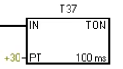
Engineer Zhang (pulling up the program segment for the sterilizer): Next is the “timer instruction”; the most commonly used in our factory is TON (on-delay timer). For example, the process requirement for the sterilizer is to maintain “121℃ for 15 minutes”; we use TON: when I0.3 (temperature signal) is closed, the timer T37 starts counting, and the preset value PT is set to “150”. Since the PLC’s default time base is 100ms, 150×100ms=15 seconds. Wait, we are using S7-200SMART, and the time base can be selected; here it should be set to “1-minute time base,” so PT=15 is correct.
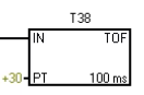
Xiao A (hastily adjusting the parameters): I previously set the time base to 100ms, and PT to 150, resulting in only counting 15 seconds, which did not fully sterilize. How do I use TOF (off-delay timer)?
Engineer Zhang: TOF is suitable for “delayed shutdown” scenarios, such as the cooling fan on the packaging line — when I0.4 (packaging machine stop signal) is disconnected, the TOF timer T38 starts counting, set for 10 minutes, and only after the time is up does Q0.2 (fan) disconnect. This way, when the packaging machine stops, the fan can continue to dissipate heat, preventing the motor from overheating. Last time, you directly cut the power to the fan, and the motor temperature exceeded 60℃, which was because TOF was not used.
4. Counter (CTU)
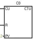
Engineer Zhang (returning to the counting issue on the packaging line): Your counting is inaccurate because the parameters for the “increment counter (CTU)” are set incorrectly! CTU has two key signals: CU (count trigger) and R (reset). Look, I0.5 (photoelectric sensor) sends a pulse every time it detects a package of cookies, triggering CU once, and the counter C0 increments by 1; when C0 reaches the preset value PV=1000, Q0.3 (full quantity alarm) is energized. But you didn’t set the “reset signal,” so when C0 reached 1000, it didn’t reset, and continued counting would cause overflow, resulting in a lower display.
Xiao A (adding a reset button I0.6): If I want to count the total packaging number per hour, do I need to use a decrement counter?
Engineer Zhang: No, you can achieve this by using CTU with a timer! For example, using T39 to time 1 hour, every hour, the contact of T39 triggers the reset of C0 while transferring the current value of C0 to D0 (data register) for storage, thus recording the output per hour. Last time, the workshop’s daily report was done this way, which is much more accurate than manual counting.
5. Comparison Instruction (CMP)
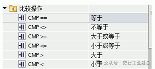
Engineer Zhang (opening the temperature control program for the fermentation tank): The “comparison instruction” is the core of process control; for example, the fermentation tank requires the temperature to be between 119℃ and 121℃, we use the CMP instruction: comparing the actual temperature (the value converted from AIW0) with 119℃ and 121℃. When the temperature < 119℃, Q0.4 (heating element) is energized; when the temperature > 121℃, Q0.5 (cooling valve) is energized; in between, both are de-energized to maintain constant temperature.
Xiao A (pointing at the ” > ” and ” < ” symbols in the program): If I want to trigger an action when the packaging quantity equals 500 packages, how do I set it?
Engineer Zhang: Just use the “equal comparison (EQ)”! Compare C0 (current packaging number) with 500; when EQ contact closes, it triggers the transfer instruction to send “2000” (corresponding to the conveyor speed of 2m/s) to the control register, and the conveyor will automatically slow down. Last time, when changing the specifications of the cookies, this was how it was implemented, without manual parameter adjustments.
6. Transfer Instruction (MOV)
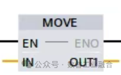
Engineer Zhang (demonstrating the operation of the MOV instruction): The “transfer instruction” is like “copy and paste”; for example, transferring the target temperature value of the fermentation tank “6050” (corresponding to 120℃) to D10 (target temperature register), comparing AIW0 (actual temperature) with D10 can achieve constant temperature control. Last time, when you adjusted the pressure parameters of the sterilizer, you manually changed the value of AIW1, resulting in program chaos; you should have used the MOV instruction to transfer the target pressure value to the register, not directly change the input value.
Xiao A: If I want to transfer multiple parameters together, such as the speed of the packaging line, target counting value, and delay time, do I need to use multiple MOV instructions?
Engineer Zhang: You can use “block transfer (BLKMOV)” to transfer parameters D0~D2 to D10~D12 at once, saving the need to write multiple MOV instructions. Last time, when the new filling machine was installed, parameters were transferred using BLKMOV, which saved programming time.
7. Addition Instruction (ADD)
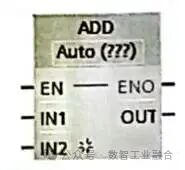
Engineer Zhang (opening the energy consumption statistics program): The “addition instruction” is suitable for cumulative calculations, such as counting the total running time of the sterilizer each day — using the TON timer to add 1 every hour, the ADD instruction adds the current value of T37 to D20 (daily cumulative time), and after 24 hours, the MOV instruction resets it to zero. Look at this program segment; D20 is now 18, representing that it has run for 18 hours today, which is much more convenient than manual record-keeping.
Xiao A: If I want to calculate the “difference,” for example, the deviation between the actual temperature and the target temperature, I can use the subtraction instruction (SUB), right?
Engineer Zhang: Correct! Use the target temperature D10 minus the actual temperature D11, storing the result in D12; if D12 > 5 (deviation exceeds 5℃), it triggers an alarm. Last time, the deviation in the fermentation tank temperature was detected promptly using the SUB instruction, which was 10 minutes faster than manual inspection.
8. Shift Instruction (SHL)
Engineer Zhang (relating to the bottle cap detection case): The “left shift instruction (SHL)” is suitable for continuous detection, such as detecting missing bottle caps on the packaging line — using 4 photoelectric sensors (I0.7~I1.2) to detect 4 consecutive bottle caps, their states are stored in D30, and the SHL instruction shifts the binary number of D30 to the left; if two consecutive “0s” (representing two missing caps) appear, it triggers Q0.6 (stop alarm). The last time you encountered a “single cap missing false alarm” was because you didn’t shift; you only detected a single sensor, and after using SHL, the false alarm rate dropped to 0.
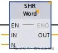
Xiao A: Does the right shift (SHR) have any use in our factory?
Engineer Zhang: Yes! For example, in the ribbon remaining detection of the label printer, using multiple proximity switches to detect the ribbon position, the SHR instruction shifts the detection status to the right; the less remaining ribbon, the fewer “1s” after the shift, and when there are less than 2 “1s,” it prompts to replace the ribbon.
Engineer Zhang (summarizing the application table of core instructions, handing it to Xiao A): Look at this table; each instruction corresponds to our factory’s actual equipment — timer controls sterilization time, counters control packaging quantity, interrupt instructions control emergency stops. When programming, first think about the process requirements, then select the corresponding instructions, and you won’t make mistakes.
Xiao A (modifying parameters according to the program): I now understand why the counting was inaccurate! One was that I didn’t add a reset signal, and the other was that I didn’t set the time base correctly. After correcting these two points, I just tested packaging 100 packages, and the program displayed exactly 100 packages! It turns out that core instructions are not isolated; they need to be combined with the process to work together.
Engineer Zhang (patting Xiao A on the shoulder): That’s right! The core of PLC programming is not memorizing instructions, but understanding the process — knowing that the sterilizer needs timing, the packaging machine needs counting, and the fermentation tank needs temperature control, then selecting the corresponding instruction combinations will naturally lead to correct programs. This afternoon, we will adjust the fermentation tank’s program; you can try using the instructions learned today, and I will watch.
Xiao A (excitedly opening the programming software): Sure, Engineer Zhang! I used to think PLC instructions were numerous and difficult, but after discussing them in relation to the equipment today, I find them simpler. I won’t be guessing in programming anymore.