Case Study: A Production Crisis Caused by Output Point Failure
“At 2 AM, a lithium battery factory’s PACK line suddenly stopped!” — When maintenance foreman Old Wang received the emergency notification, the production line had already been halted for 1 hour, with each minute of delay costing 3000 yuan. Upon investigation, it was found that the Q0.2 output point of the Siemens S7-1214C PLC was not outputting a signal, which controlled the feed cylinder of the ear welding machine. A backup PLC module needed to be dispatched from another location, taking at least 4 hours to arrive.
Have you encountered a similar dilemma? The PLC output point serves as a “bridge” connecting control logic to actuators. Once damaged (such as a burnt transistor or a stuck relay contact), it can lead to equipment downtime or, in severe cases, result in the scrapping of batches of products. In this article, we will systematically explain 5 highly practical solutions from emergency handling → on-site repair → long-term prevention, accompanied by module disassembly repair videos and an engineer’s pitfall avoidance guide, so you won’t be at a loss when facing output point failures.
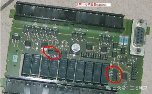

3-Minute Emergency Replacement Method: Quickly Restore Production Using Backup Points
When an output point suddenly fails and no spare parts are available, the backup point replacement method is the most direct solution, applicable to transistor/relay output PLCs, taking an average of no more than 10 minutes.
Operational Steps (Taking Siemens S7-200 SMART as an Example)
- Fault Point Confirmation: Use a multimeter in diode mode to test the output point against the COM terminal. If the transistor output point is conducting in both directions (it should normally conduct in one direction only), or if the relay output point is not conducting/always conducting, it can be determined as damaged.
- Program Modification: Search for the fault point in the software (e.g., Q0.1) and replace all logic calling that point with the backup point (e.g., Q0.5), ensuring to synchronize modifications in the symbol table comments.
- Hardware Wiring Adjustment: Move the control line of the actuator from the fault point terminal block to the backup point, ensuring the wire numbers correspond with the drawings (it is recommended to relabel using a label maker).
- Testing and Verification: Force output from the backup point and observe whether the actuator operates normally, using an oscilloscope to detect the signal waveform (it should normally be a 24V square wave without noise).
Advantages: No additional cost, production can be restored in as fast as 3 minutes; Limitations: Dependent on the number of backup points, long-term occupation of backup resources may pose hidden risks.
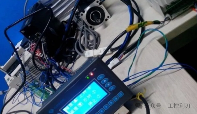
External Relay Expansion Method: Achieve “Permanent Replacement” at Low Cost
If the PLC has no spare output points, or if there are multiple fault points (such as batch module failures), the external relay expansion method is a more reliable choice. By adding intermediate relays, the PLC output signal can indirectly control the load, avoiding direct driving of high-power devices that could overload the output point.
Solution Design (Taking Mitsubishi FX5U PLC as an Example)
| Component | Model Specification | Function |
|---|---|---|
| Intermediate Relay | Omron MY4N-GS DC24V | Isolate PLC output from the load, withstand large currents |
| Surge Protector | Phoenix VIP-20-C/2-FM | Absorb back EMF from inductive loads |
| Terminal Block | Weidmüller UK 2.5N | Standardize wiring for easier maintenance |
Wiring Key Points
- PLC output point (Y0) connects to the positive terminal of the relay coil, and the negative terminal connects to the PLC COM terminal;
- The relay normally open contact connects to the load power supply (e.g., AC220V), with the load side in series with the surge protector;
- Key Technique: Connect a 1N4007 diode in parallel across the relay coil (reverse parallel) to suppress reverse voltage spikes when power is cut off.
Application Case from a Food Factory: The PLC output point of the packaging machine frequently burned out (due to directly driving a 220V solenoid valve). After adopting the relay expansion, the output point failure rate dropped from 3 times a month to 0, saving 12,000 yuan in module replacement costs annually.
Module Repair Method: 30 Yuan Component Revives a Thousand Yuan Module
For transistor output modules (such as Siemens SM 1222), most failures are due to burnt output transistors, which can be repaired at low cost by replacing components. You will need a soldering iron, multimeter, hot air gun, and a transistor of the same model (e.g., TIP122, BD243C).
Repair Steps (Taking SM 1222 Module as an Example)
- Module Disassembly: Remove the 4 screws securing the module casing, separate the PCB, and be careful to protect the ribbon cable interface;
- Fault Component Location: Find the corresponding transistor based on the output point terminal number (usually marked Q1, Q2…), use a multimeter to check the ce terminal conductivity; damaged components will show a short circuit;
- Component Replacement: Use a hot air gun to blow off the damaged transistor, clean the pads, and solder the new component (pay attention to the pin order to avoid reverse connection);
- Insulation Treatment: Apply 704 silicone rubber on the surface of the component to prevent vibration from causing pin detachment;
- Function Testing: Reinstall the module into the PLC, force output through programming software, and use an oscilloscope to check if the signal is normal (normal output voltage fluctuation should be ≤±0.5V).
Risk Warning: If the PCB copper foil inside the module is burnt or the CPU board is faulty, it is not recommended to repair it yourself; it should be sent back for factory repair.
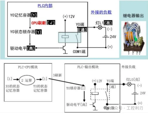
Program Optimization Method: Avoid Output Point Overload from a Logical Perspective
80% of output point failures stem from long-term overload or frequent on-off cycling, and program optimization can reduce the probability of damage from the source. The following 3 programming techniques have been validated effective in over 100 factories:
1. Output Point Overcurrent Detection
Add current detection logic in the program: when the load current exceeds the rated value (e.g., transistor output point ≤0.5A), trigger an alarm and cut off the output. For example, with Schneider M340 PLC, collect load current through an analog module and execute protective actions based on comparison with the set value.
2. Pulse Output Distribution
High-frequency on-off loads (such as high-speed solenoid valves) accelerate output point aging; pulse signals can be distributed across multiple output points to work alternately. For example, change the original 10Hz pulse signal controlled by Q0.0 to alternate outputs from Q0.0 and Q0.1, reducing the single point on-off frequency to 5Hz.
3. Output Point Status Monitoring
Design an output point status monitoring screen in the HMI interface to display real-time voltage, current values, and cumulative on-off counts for each point. When a point approaches its lifespan threshold (e.g., relay output point 100,000 times), provide early warning for replacement.
Preventive Maintenance Method: Extend Output Point Lifespan by 3 Times with 6 Details
“The best maintenance is prevention,” summarizes a senior engineer’s output point maintenance checklist, which is recommended for collection and execution:
| Maintenance Item | Frequency | Standard Requirements |
|---|---|---|
| Output Point Load Detection | Once a month | Measure actual current with a clamp meter, not exceeding 80% of the rated value |
| Terminal Tightening | Once a quarter | Tighten with a torque wrench to 0.8N·m |
| Module Dust Cleaning | Once every six months | Blow out cooling holes with compressed air (0.3MPa) |
| Surge Protector Status Check | Once a month | Indicator light should be green; red indicates replacement needed |
| Ground Resistance Testing | Once a year | System ground resistance ≤4Ω, module ground ≤1Ω |
| Output Point Rotation Usage | Once every six months | Swap long-idle backup points with commonly used points in logic |
Ending Interaction: What is Your Solution for Output Point Failures?
PLC output point failures are common, but as long as you master the five-level handling logic of “emergency replacement → external expansion → module repair → program optimization → preventive maintenance,” you can minimize losses. A certain automotive welding workshop reduced the average output point failure handling time from 90 minutes to 15 minutes using the solutions in this article, saving over 500,000 yuan in downtime losses annually.
Have you encountered output point failures in your work? What clever methods did you use to solve them? Feel free to share your practical experiences in the comments section.

Previous Recommendations
Students’ companies are hiring electricians for maintenance!
Listed companies are hiring! 【20 After-sales Electrical Engineers】
10 Years of Engineer Summary: 5-Step Method for PLC Fault Diagnosis, Reducing Downtime Loss to Zero!
Hiring Electrical Engineers (New Energy Industry) 13K-19K
5 PLC Programming Examples, Advanced Electricians’ Level, Understand and You Can Ask for a Raise!
Learn Analog Control from 0 to 1, Just One Temperature Control Case to Master It!
Valuable Sharing! Comprehensive Analysis of Wiring Diagrams and Program Cases for Major PLC Brands!
24 Types of Sensor Wiring Complete Guide: From Beginner to Expert, Essential Tool for Engineers!
Can Projects from Different Versions of TIA Portal Be Opened Directly? After Reading This Article, You Will Know!
5 Fatal Pitfalls Encountered While Learning PLC! The 3rd One Cost Me 3 Months of Work【Beginner’s Must-Read Pitfall Guide】
Top 10 Sensors Every Electrician Must Learn! If You Don’t Understand, You’re Out!
Experienced Drivers Take You Quickly into PLC Control Servo Positioning Learning, Get On Board!
Stop Changing Processes Blindly! 150 Process Flow Diagrams, A Bloody Summary That Boosted Factory Efficiency by 300%
Stop Just Reading Books! 11 Methods for Mitsubishi PLC Dual Button Control of Motor Start and Stop, Beginners Can Just Copy!
These Electrical Schematic Diagrams Are Enough to See Once: From Basic Symbols to Industrial Applications, All Analyzed!