Exploring the ‘Digital Brain’ of Factories: PLCs and Data RegistersWhy do factories need a “brain”? In modern production lines, when robotic arms accurately grasp parts, conveyor belts deliver materials in sync, and inspection devices monitor quality in real-time, what is behind the unified command of all this? The answer lies at the core of every smart factory —PLC (Programmable Logic Controller). This industrial control device, known as the “digital brain,” is making complex production processes as precise and reliable as clockwork through countless invisible data flows.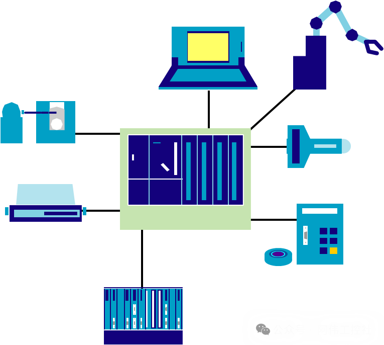 If we compare the PLC to the “central control room” of a factory, thenData Register D is the busiest “smart filing cabinet” within the control room. It not only temporarily stores real-time data during production (such as current speed and temperature readings) but also long-term retains equipment parameters (like motor rated power and sensor calibration values), and must also record system status in real-time (such as error codes and running time). These functions may seem simple, but they are the “nervous center” of industrial automation — without the orderly storage and retrieval of data, even the most powerful “brain” would become a “forgetful conductor.”The Wisdom of Storage in LifeThe data management logic in factories is actually akin to household storage:
-
Refrigerator corresponds to long-term parameter storage (such as equipment model and factory settings)
-
Drawer corresponds to temporary data caching (such as production count variables)
-
*Safe corresponds to important status records* (such as fault logs and safety thresholds) Data Register D integrates these three functions into a smart storage system, ensuring that factory data is organized.*
As the core component for data processing in PLCs, Data Register D’s role goes far beyond simple storage*. In the Mitsubishi FX3U series PLC*, special data registers (D8000-D8009) can monitor scan timebattery voltage, and even error states; in a 12-axis servo-controlled production line*, it records encoder pulse counts to achieve millimeter-level positioning*; in analog control systems*, it stores continuously varying physical quantities such as temperatureand pressure values. It can be said thatevery precise control and every state feedback* from the PLC relies on the “silent contribution” of the data register. From the robotic arm’s grasping commands to the coordinated operation of the entire production line*, this invisible “digital steward” in the factory is ensuring that the industrial automation “brain” remains alert and precise through its efficient data management capabilities. What is Data Register D? — The Industrial Password in the Filing CabinetImagine a row of neatly arranged smart filing cabinets in the central control room of a factory — this is a true depiction of PLC Data Register D. These cabinets do not store tools or documents like ordinary filing cabinets; instead, they store the “digital passwords” of industrial production: from the hourly output of the production line, the real-time temperature of the furnace, to the running time of the robotic arm, and even the error codes during equipment failures, all are securely stored in these special cabinets labeled “D+number”..Each filing cabinet has a unique number, such as D0, D100, D8000, etc., just like the door numbers of filing cabinets, allowing the PLC to accurately locate the required data. The “capacity” of the cabinets is also divided into two types:Single-cell cabinets are 16-bit storage units that can hold integers between -32768 and +32767, with the highest bit acting as a “positive-negative label” to determine whether the value is positive or negative; if larger numbers are needed, such as the annual total output of the entire production line, two adjacent single-cell cabinets can be combined intodouble-cell cabinets, forming a 32-bit storage unit, which expands the storage range to -2147483648 to +2147483647.These “smart filing cabinets” can store more than just numbers. They function like the factory’s “universal filing cabinet,” capable of storing characters, ASCII codes, BCD codes, and various data types, and can perform complex operations such as arithmetic calculations, logical comparisons, and data shifting in conjunction with the PLC. For example, the counter values on the production line are first stored in the D register and then “moved” to the display screen for workers to view using the MOV instruction.Different Types of “Filing Cabinets” Each Have Their Own Functions: The blue cabinets are general-purpose, temporarily storing intermediate data during production, and will “clear” when power is lost; the green cabinets are retain-type, like a locked cabinet for valuables, which can retain data even when power is lost; the orange cabinets are special types, such as D8004, which specifically records battery voltage, D8006, which detects sudden power outages, and D8000-D8009, which will also “remember” system error information, making them the factory’s “black box”..It is these seemingly ordinary “digital filing cabinets” that constitute the “memory center” of the PLC. They silently store and manage the core data of industrial control, ensuring that every device and every process can operate precisely according to the “password” — this is Data Register D, the most inconspicuous yet crucial “invisible steward” in the factory.Storage Mode Showdown: Which is Better, 16-bit or 32-bit?If we compare the PLC’s data registers to the factory’s “storage containers,” then the 16-bit and 32-bit modes are like two different specifications of storage tools: the blue “small cup” on the left is labeled “16-bit,” with a capacity scale accurate to -32768~32767, just enough to hold the production line’s part count (such as producing 2000 parts per hour) or short-term timers (like a 10-minute process interval); the orange “big bucket” on the right is the “32-bit” mode, with a capacity expanded to -2147483648~2147483647, sufficient to accommodate the total annual output of the entire production line (such as 5 million pieces) or the three-dimensional coordinate data of robots (like X-axis positioning value of 12345.67 millimeters). The bidirectional arrow in the middle reveals a clever design — two “small cups” can be combined into one “big bucket” by linking two adjacent 16-bit registers (like D0 and D1) to create 32-bit storage capacity..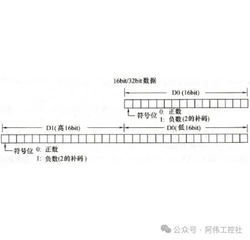
 Core Parameter Comparison TableTableCopy
| Feature | 16-bit Register | 32-bit Register (Double Word) |
|---|---|---|
| Storage Capacity | 2 bytes (16 bits) | 4 bytes (32 bits) |
| Value Range | -32768~32767 | -2147483648~2147483647 |
| Typical Application Scenarios | General counters, short-term timers (like Mitsubishi FX3U series D8030 timer interrupt values) | High-precision analog data acquisition (temperature, pressure), robot walking coordinates, cumulative production output |
| Combination Method | Single register used independently | Two adjacent registers combined (like D1 high 16 bits + D0 low 16 bits) |
Key Differences Summary: The 16-bit mode, with its lightweight 2-byte size, has advantages in resource usage and instruction execution speed, making it suitable for storing switch states, simple counting, and other “daily tasks”; the 32-bit mode, on the other hand, meets complex control needs by expanding the value range and precision, but requires two 16-bit address spaces. Just as a factory would not use only one specification of container, the PLC will flexibly choose storage modes based on data scale — there is no absolute “better,” only “more suitable.”In practical applications, this “on-demand selection” logic is particularly important. For example, in Mitsubishi PLC programming, 16-bit registers are often used to store single-precision parameters (like timer values from 0 to 65535), while when high-precision displacement (like 12345678 pulses of motor operation) or long-term cumulative data (like annual production days) needs to be recorded, the 32-bit mode formed by combining two 16-bit registers becomes a necessity. This flexible storage strategy is one of the core capabilities of the PLC as a “digital steward” for efficiently managing factory data.Function Classification: Three Types of Registers Each Show Their Skills## Function Classification: Three Types of Registers Each Show Their SkillsImagine in the data management center of a factory, the PLC’s registers are like a finely divideddocument management system: the left side is the temporary file cabinet, the middle is the constant temperature and humidity safe, and the right side is the real-time updated system logbook, corresponding to three types of data registers with different functions. Through this analogy, we can quickly grasp their respective “job responsibilities” [Insert image 3: PLC register classification diagram (three-column infographic showing general, retain, and special registers with data ranges labeled D0~D199, D200~D7999, D8000~D8255, characteristics, and icons)].### Temporary File Cabinet · General Data Registers (D0~D199)Open file cabinets covered with sticky notes, specifically storingtemporary calculation data. This set of cabinets has 200 drawers (D0~D199), where intermediate calculation results and temporary counts from the production line are circulated. But be aware of its “amnesia” — when the PLC switches from running (RUN) to stop (STOP) state6, all sticky notes will automatically clear10. However, pressing the “M8033” special “clip” can temporarily fix important sticky notes to prevent loss.Key Parameter OverviewAddress Range: D0~D199 (200 points total)Data Lifecycle: Temporary storage, defaults to zero when power is lost or stoppedSpecial Function: Data can be retained when M8033=ONApplicable Scenarios: Intermediate calculation results, temporary counts### Safe · Power Retaining Data Registers (D200~D7999)In the data safe with battery backup, 7800 drawers (D200~D7999) store the factory’s most core “business secrets.” Here, data such as cumulative production counts3, process parameter formulas, etc., are stored, and even in the event of sudden power outages or system reboots, they can remain safe like deposits in a bank safe. Technicians can even flexibly adjust the actual usable range of this safe drawer through parameter settings.Core Advantage AnalysisAddress Range: D200~D7999 (7800 points total)Safety Feature: Built-in power retention mechanism, data permanently savedTypical Applications: Equipment operation count statistics, product qualification rate parametersExpansion Capability: Effective storage range can be adjusted through system parameters7### System Logbook · Special Data Registers (D8000~D8255)Embedded in the console is a black logbook with a gear lock, containing 256 pages (D8000~D8255) automatically filled by the PLC system. Unlike the previous two types of cabinets, which can be accessed freely, it focuses on recordingsystem-level operational status:
-
Time Manager D8013: The “second hand” that ticks every second, providing a precise time reference pulse for the production line
-
Safety Alarm D8005: When the system backup battery voltage is too low, it will immediately highlight the alarm in red in the log
-
Health Recorder D8022: Real-time records the PLC’s “heartbeat frequency” — program scan cycle (ms)
These special pages include some read-only archives (like system status), while others allow administrators to write configuration parameters, but unmarked blank pages are strictly prohibited from being altered.Star Register Illustrated
| Address | Function Nickname | Practical Value |
|---|---|---|
| D8013 | 1-second pulse generator | Timing control, second-level counting |
| D8005 | Battery Doctor | Advance warning of power failure |
| D8022 | Heartbeat Monitor | Optimize program running efficiency |
| D8000 | System Control Console | Store operational monitoring parameters |
Through the division of this “document management system,” the PLC achievesprecise hierarchical management of data storage: temporary data is used as needed, critical data is securely retained, and system data is monitored in real-time. Remember this “filing cabinet-safe-logbook” analogy, and you can accurately find the “dedicated storage space” for each type of data during programming.The “Data Steward” in Industrial Sites: Real Application CasesIn an automated production line for automotive parts, from loading metal blanks to finished product inspection, the PLC data registers are silently operating in the role of “data steward.” The core data link of this production line is clearly presented as:Left-side sensor group collects real-time signals → Middle PLC controller’s data registers store and process → Right-side actuators execute actions, with the three forming a closed loop through orange data flows, like the “nervous network” of the factory transmitting commands.Sensor → Register: The “Receiving and Classifying” of DataWhen the conveyor belt carries parts past the photoelectric sensor at the entrance (I0.0), the sensor transmits the “part passed” signal to the PLC. At this point,Data Register D0 immediately activates the counting function — every time a part is detected, the value of D0 automatically increases by 1, accurately recording the “number of parts processed today.” This real-time counting capability stems from the register’s “instant storage feature,” ensuring that even in the event of a sudden power outage, the data in D0 will not be lost, just like a supermarket cash register’s “account book” never misses a transaction.Continuing forward, the RTD PT100 temperature sensor at the welding station converts temperature signals from -250 to 650°C into digital quantities, which are stored inD200 temperature parameter register using the MOV instruction. The system will automatically divide the raw data in D200 by 82 (each degree Celsius corresponds to 82 digital quantities) to calculate the actual temperature value. When the value falls below the preset 180°C, the PLC immediately drives the heating tube actuator to heat up; if it exceeds 220°C, it cuts off the power, ensuring that the welding point temperature remains stable within a ±2°C error range.Core Logic of Data Flow: The raw signals collected by the sensors (such as part counts and temperature values) must first be “translated” into register-recognizable digital quantities through PLC instructions (like the MOV transfer instruction) before being stored in the corresponding registers (like D0, D200), completing the transformation from “physical signals” to “digital assets.”Register → Actuator: The “Dispatch and Execution” of InstructionsIn the robotic arm’s grasping phase at the end of the production line,Special Data Register D8013 plays the role of a “metronome.” The 1-second pulse signal it provides controls the robotic arm to read the counting data from D0 every 5 seconds: when D0 accumulates to 50 parts, D8013 triggers the robotic arm to execute the “grasping-stacking” action; at the same time, it records the current time through D8019 (real-time clock hour register), storing the information “14:30 completed stacking of the 500th part” in the production database.This collaborative operation is even more critical during exception handling. If a sensor at a certain workstation detects a part defect (triggering I0.2), the PLC will immediately write the “defect signal” intostatus flag register D10. At this point, the 3rd bit (bit3) of D10 is set to 1, and the conveyor actuator receives the signal from D10 to automatically stop, while the alarm light flashes — the entire process from signal detection to execution action takes only 0.3 seconds, preventing defective products from flowing into the next process.The Management Philosophy of the “Data Steward”These registers, while having different functions, follow a unified “management logic”: D0 focuses on “quantity recording,” D200 is responsible for “parameter control,” D8013 manages “timing scheduling,” and D10 serves as “exception warning.” They are like the “functional departments” of the factory: some manage production statistics, some manage process parameters, and some manage scheduling, collectively supporting the efficient operation of “producing 600 qualified products per hour.”From the “paper ledger era” of manually recording production data to the “digital twin era” of real-time updates in registers, PLC data registers are ensuring that every piece of data in the factory is traceable, and every decision is based on evidence — this vividly illustrates the “data-driven production” of the Industrial 4.0 era.Conclusion: How Data Registers Empower Smart ManufacturingIn the wave of Industrial 4.0, PLC data registers, as the “digital steward” of smart manufacturing, have become the core link connecting physical devices and digital systems with their powerful data management capabilities. Whether it is the real-time collection of sensor parameters, precise recording of equipment status, or dynamic switching of production formulas, data registers are silently supporting every precise control and efficient collaboration on the industrial site. Their three core capabilities provide a solid foundation for the flexibility, precision, and intelligence of smart manufacturing.Three Core Capabilities: From Data Storage to System EmpowermentClassified Storage: Through the functional division of general registers (temporary data processing), power-retaining registers (critical parameter memory), and special registers (self-monitoring of devices), data registers achieve full-scene adaptation in industrial scenarios. For example, in logistics conveyor systems, general registers record conveyor belt running speeds in real-time, power-retaining registers save batch production counts, while special registers monitor key status parameters like motor temperature, ensuring that data management in every link is appropriately handled.Elastic Capacity: The 16-bit and 32-bit storage modes flexibly adapt to different data needs. The 16-bit register is suitable for basic counting (like product quantity statistics), while the 32-bit mode supports high-precision control (like robot trajectory coordinate calculations and floating-point operations of flow sensors). In Mitsubishi Q series PLC production lines, this elastic capability allows devices to simultaneously handle simple action sequences and complex process parameters, achieving millisecond-level switching of 100 production formulas..System Collaboration: As the “nerve center” of industrial data flow, data registers push real-time data to ERP systems through protocols like Cascadas, supporting automatic generation of production reports and fault analysis; at the same time, they utilize special registers for self-diagnosis of devices (like battery voltage monitoring and power outage detection). In industrial robot workstations, this collaborative capability ensures seamless synchronization of robotic arm actions with production line rhythms, advancing the factory from standalone automation to overall intelligence.Industrial Knowledge: The “Memory Password” of Power Outages and RestartsWhen a production line suddenly loses power, why can it immediately resume precise operation after restarting? The answer lies in thepower-retaining registers. These special “memory units” continuously save production parameters (such as current process progress, equipment calibration values, alarm thresholds), ensuring that data is not lost even in a power-off state. As demonstrated in the practical application of Mitsubishi PLCs, retaining registers act like the factory’s “digital memo,” ensuring that every restart can seamlessly connect to the breakpoint, avoiding production interruptions and quality fluctuations caused by data loss.From the storage of individual sensor data to the collaborative operation of the entire production line, data registers inject the core driving force of data-driven manufacturing in a “subtle and silent” manner. This “digital steward” hidden in the PLC is quietly changing the future of industrial control. Phone Number: 15622894345 Scan the QR code to receive materials