
Click the top to follow us!
 Introduction: Why do temperature sensors always “lie”?


A food factory’s constant temperature furnace clearly displays 25.7℃ on the screen, but when maintenance personnel measure it with an infrared thermometer, the actual temperature has soared to 30℃—such “digital lies” are not uncommon in industrial sites. When the production line is forced to stop due to temperature control issues, engineers spend half a day troubleshooting only to find that the sensor hardware is intact and the program logic is fine. Where does the problem lie?
The truth often lies in the “language barrier” of data: The signal output from the temperature sensor needs to be converted from analog to digital (A/D) to become a digital quantity, but the sensor may transmit data in integer (INT) format, while the PLC’s PID control algorithm requires floating-point numbers (REAL) for precise calculations. It’s like two people speaking different dialects; the difference in storage formats between integers and floating-point numbers turns what should be an accurate temperature value into a “confused account”.
The cost of this “language barrier” can be heavy. A temperature control system once caused a production line to stop for several hours due to incorrect data type conversion. It was later found that the engineer directly added an integer (INT) to a floating-point number (REAL), resulting in abnormal temperature displays and nearly causing a program crash.1Moreover, a more insidious problem lies in the loss of precision: when storing temperature values using integer types (INT), the decimal values are directly truncated, and 25.7℃ may be treated as 25℃. The accumulated error over time is enough to turn the constant temperature furnace into a “time bomb”.1.
When the sensor’s integer signal meets the PLC’s floating-point operations, it’s like using a meter stick to measure a hair strand—it’s not that the tool is bad, but the “measurement unit” is not chosen correctly. To unravel the mystery of the temperature sensor’s “lies”, we must start with the most basic “industrial language syntax” of data types.
 Data Type ABC: Understanding the PLC’s “Data Storage Cabinet”


16-bit Integer (INT)
If we compare PLC data storage to organizing a workshop storage cabinet, then16-bit integer (INT) is like a drawer labeled with positive and negative—the entire drawer is evenly divided into 16 compartments, with the top compartment (most significant bit) labeled “positive or negative”: a label of 0 indicates storage of positive numbers, while a label of 1 indicates negative numbers, and the remaining 15 compartments are used to record specific values.This “label + value” design allows INT to represent both positive and negative numbers, making it the main player in handling small-range integers in PLCs.
How to Store Numbers in the Drawer? Understanding Storage Logic with Binary
For the value +34, its storage method in the INT drawer is as follows: the most significant bit (15th bit) is labeled “0” (positive label), and the remaining 15 compartments use binary to represent the value of 34. Since 34 = 32 + 2 = 2⁵ + 2¹, the corresponding binary is <span><span>0000000000100010</span></span>—the leading zeros are to fill up the 15 value compartments.If it is a negative number, such as -34, the most significant bit will change to “1”, and the value part will be represented in two’s complement (this is the PLC’s internal automatic handling of “digital packaging”).
INT Core Parameter Overview
-
Storage Occupancy: 1 word (16 bits), equivalent to 2 bytes
-
Sign Rule: The most significant bit is the sign bit (0=positive, 1=negative)
-
Value Range: -32768 ~ 32767 (signed); if the sign bit is removed (unsigned UINT), then it is 0 ~ 65535
What Scenarios are Suitable for Using INT? From Packaging Machines to Sensor “Counting Experts”
INT is best at handlingsmall-range discrete values, such as product counting in automatic packaging machines: when a sensor detects a product passing (triggered by X0 signal), the program executes <span><span>ADD D100</span></span> instruction, allowing the INT type register D100 to accumulate by 1.Since the daily production is usually within tens of thousands, the upper limit of INT, 32767, can fully cover it, avoiding waste of storage space while quickly responding to counting needs. Additionally, integer signals from devices like temperature sensors and flow sensors are often transmitted using INT, such as ambient temperatures ranging from -20℃ to 50℃, which can be stored accurately and efficiently using INT..
Beware of “Drawer Overflow”: Overflow is INT’s Hidden Trap
If you force 32768 into the INT drawer, what will happen? It’s like pouring 15 liters of water into a 10-liter bucket—overflow will cause the value to “burst” beyond the storage range, resulting in unexpected outcomes (for example, 32768 will display as -32768).8In practical engineering, for instance, if the production line count exceeds 30,000, using INT for storage may lead to bizarre situations where “35000 units were produced, but the PLC shows -28536”. This is also why we will focus on how to avoid such problems through data type conversion (like INT to DINT) in the subsequent “Pitfall Guide”.
Through this “labeled drawer”, we can intuitively understand the design logic of INT: it is not a universal storage container, but a “high-efficiency storage box” tailored for small-range integer scenarios. The key to using it well lies in remembering the “drawer capacity” and avoiding the overflow red line.
32-bit Integer (DINT)
If we compare 16-bit integers (INT) to a “single drawer” that can only hold small items, then 32-bit integers (DINT) are like a large drawer formed by two horizontally connected INT drawers—it achieves a leap in value storage capacity by integrating the storage space of two 16-bit registers (a total of 4 bytes). This “expansion” feature allows DINT to easily accommodate large values like 100,000 without worrying about the awkwardness of “small drawers not fitting large items”..
1. Looking at Range Differences from “Drawer Capacity”
The value range of 16-bit INT is only -32768 to 32767, like a drawer that can hold a maximum of 30,000 items; while DINT, as a signed double integer, has a value range of **-2147483648 to 2147483647** (unsigned can reach 0 to 4294967295), equivalent to a super storage space that can hold 2.1 billion items.This difference is crucial in practical applications: for example, if a production line has a daily output of 1,000 units, after one year, the cumulative output reaches 365,000, at this point, INT would have long overflowed and reported an error, while DINT’s “large drawer” can easily handle it..
Key Difference: In DINT’s 32-bit storage space, bits 0 to 30 are used to represent values, while the most significant bit (31st bit) is specifically marked for sign (0 for positive, 1 for negative). This structure ensures both value precision and compatibility with the rules of binary two’s complement arithmetic..
2. Storage and Conversion Techniques of “Drawer Splicing”
The “two drawers” of DINT are not simply stacked: when expanding a 16-bit INT to a 32-bit DINT (such as through WTD or ITD instructions), positive integers will have 0 filled in the high drawer, while negative integers will be filled with 1 according to the characteristics of two’s complement. For example, in S7-200 SMART, if the 16-bit integer of counter C10 needs to participate in large value calculations, it can be converted to DINT and stored in AC1 using the I_DI instruction to avoid overflow during the process.
In practical applications, it is important to note: if converting DINT back to INT (such as using DTI instruction), if the value exceeds the INT range, the PLC will trigger the SM1.1 overflow flag, and the output value will remain unchanged. This is like forcibly stuffing items from a large drawer into a small drawer; once overloaded, it will get “stuck”.
3. Typical Application Scenarios and Advantages
DINT, with its high precision and large span, is widely used in scenarios requiring long-term accumulation or precise calculations:
-
Production line counting: such as the number of car bodies passing through the assembly line (annual production capacity of 100,000 units)
-
Energy measurement: cumulative power generation, water consumption (can reach millions of kilowatt-hours per month)
-
Motion control: servo motor position feedback (high precision pulse counting)
In terms of data storage, the addressing method for DINT varies slightly among different PLC brands: in S7-1200/1500, it can be directly defined as a DINT variable in a DB block, while Mitsubishi FX series requires specifying two consecutive data registers (such as D0 and D1). However, regardless of the method, its core advantage remains using the 32-bit “large drawer” to solve the bottleneck problem of small capacity data types..
Single Precision Floating Point (REAL)
If we compare PLC data types to drawers in a toolbox, then single precision floating point (REAL) is the one labeled “scientific notation”—it can store not only integers like the integer drawers but is specifically designed to accommodate values with decimal points. The internal structure of this drawer is quite sophisticated: the outermost layer is labeled “positive or negative” (sign bit), the middle layer contains the “decimal point position adjuster” (exponent), and the innermost layer is filled with the “significant digit storage area” (mantissa), which together can package various decimals into 32-bit binary data..
For the decimal value of 12.25, its binary “packaging” in the REAL drawer is<span><span>0 10000010 10001000000000000000000</span></span>. The leftmost “0” is the sign bit (indicating a positive number), the middle 8 bits “10000010” is the exponent (equivalent to moving the decimal point 3 places to the right), and the rightmost 23 bits “10001000000000000000000” record the significant digits. This structure allows REAL to easily represent a range from ±1.175495E-38 to ±3.402823E+38, like a telescopic drawer that can hold both elephants and ants..
Industrial temperature sensors are typical users of REAL. For example, in an environmental monitoring system requiring 0.1℃ precision, the sensor returns data like 25.6℃ and 30.2℃. Using integer types would lose the information after the decimal point, while REAL can fully store these “tail-bearing values”. In PLC programs, you might see snippets like:<span><span>MOV K10.0 D0 // Set initial temperature to 10 degrees</span></span>, where D0 is defined as a REAL type storage area, specifically interfacing with analog signals..
Key Features: REAL uses 32 bits to achieve the dual capability of “large range + decimal representation”, but the 23-bit mantissa limits its precision to 6-7 significant digits, and when converted to integers, the decimal part will be directly truncated..
However, this “universal drawer” also has its shortcomings—its “significant digit storage area” is only 23 bits, which means it can retain about 6-7 significant digits in decimal. This implies that if it stores “123456.789”, the trailing “89” may be rounded off; more troublesome is that when using the CONV instruction to convert REAL to integer, the decimal part will be directly “cut off”, for instance, 10.9 will become 10 instead of 11. This “large range but limited precision” characteristic is like using a fishing net with slightly large mesh; it can catch big fish but may miss small ones—this is also the root of precision loss issues in subsequent data conversions..
 Conversion Instruction Practice: The Operator’s Manual for Data “Translators”


Integer to Floating Point: FLT and DFLT Instructions
If we compare PLC data processing to office file management, then the FLT instruction is like a clerk labeling integer files with “decimal tags”—it does not change the value size but can change the data format from “integer file” (INT) to “decimal file” (REAL). For example, when the data register D0 stores the integer 20, executing<span><span>FLT D0 D2</span></span> instruction will cause D2 and D3 to jointly store the floating-point result of “20.0”. This is like a thick file needing to be stored in two storage cabinets in layers because REAL type data essentially requires 32-bit format, occupying two 16-bit registers’ “storage space”..
However, the “clerk’s” capabilities have limits: the FLT instruction can only handle 16-bit “small files” (INT type), and when encountering 32-bit “large files” (DINT type), a more advanced “translator” is needed— the DFLT instruction. For example, to convert the 32-bit integer stored in D10-D11, you must use<span><span>DFLT D10 D12</span></span> instruction, storing the result in D12-D13. If you use FLT to process 32-bit data, it would be like asking an intern to translate a large document; the data may be truncated or erroneous, and in severe cases, it could cause the entire control process to “jam”.
Key Matching Principles
-
FLT ↔ 16-bit integer (like a single register D0)
-
DFLT ↔ 32-bit integer (like consecutive registers D10-D11) Both target storage are 2 consecutive registers (REAL type), but the input data’s “bit specifications” must strictly correspond; otherwise, conversion errors may occur.
In mainstream PLCs like Mitsubishi FX2N, the standard format for the FLT instruction is<span><span>FNC49 FLT [S] [D]</span></span>, where [S] is the integer source, and [D] is the starting address for the floating-point target. In actual programming, it is recommended to monitor visually through ladder diagrams: when the trigger condition (like X010) is activated, observe whether D2-D3 accurately displays results like “20.0”; this is the “gold standard” for verifying conversion correctness.
Floating Point to Integer: INT and DINT Instructions
In PLC data type conversion, converting floating point to integer is like “tailoring” the data— the INT instruction is like directly tearing off the decimal part’s label; regardless of whether the decimal is 0.1 or 0.9, only the integer part is retained. For example, converting 3.9 to INT will directly truncate it to 3, making it the first choice in simple scenarios. In contrast, the ROUND instruction is more like a “rounding tailor”; it will decide whether to carry over based on the decimal part. Thus, 3.9 processed by ROUND will yield 4..
This difference is crucial in practical applications. For instance, in a temperature control system, if the target value is set to 3.5℃, using the INT instruction will truncate it to 3℃, potentially leading to insufficient heating; while the ROUND instruction will round it to 4℃, which is closer to the expected control precision. In scenarios requiring precise control (like constant temperature incubators), the ROUND instruction can effectively reduce control deviations caused by truncation..
From a data length perspective, the INT instruction outputs a 16-bit integer (range -32768 to 32767), while the DINT instruction outputs a 32-bit integer (range -2147483648 to 2147483647). It is particularly important to note that when the conversion value exceeds the target integer range, it will trigger an overflow— for example, converting a floating point value of 40000.0 to INT will exceed the 16-bit integer limit, causing the PLC to set the overflow flag (like SM1.1), and the output value will remain unchanged, potentially leading to system misjudgment..
Key Difference Overview
-
INT instruction: truncation (3.9→3), 16-bit output, higher overflow risk
-
ROUND instruction: rounding (3.9→4), usually outputs 32-bit double integer
-
Core Principle: prioritize precision with ROUND, prioritize range with DINT, and use INT for simple truncation
Different PLC brands have slight variations in instruction implementation: Siemens S7-1200/1500 series separates TRUNC (truncation) and ROUND instructions, while Mitsubishi FX series directly assigns truncation functionality to the INT instruction. However, regardless of the model, pre-conversion range checks are key to avoiding pitfalls—like confirming dimensions before tailoring data, this step will be elaborated in the subsequent “Pitfall Guide”.
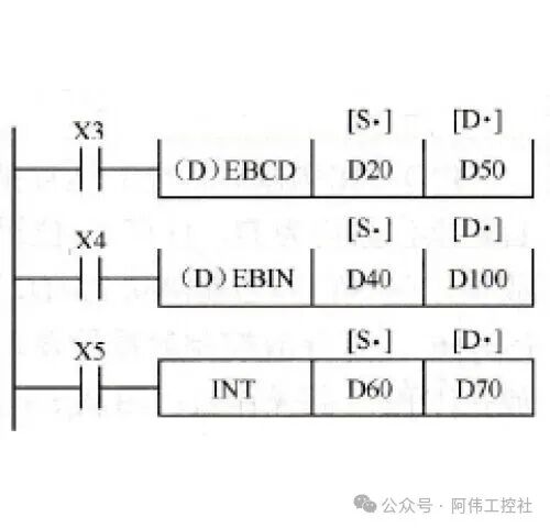
The above image illustrates a typical floating point to integer conversion process. For example, when inputting the REAL value stored in D60-D61 using the INT instruction, the system will directly truncate the decimal part and store the result in D70. Throughout this process, it is essential to monitor the overflow flag status to avoid control anomalies caused by data exceeding the range.
 Storage Rules Revealed: The Logic of Register “Storage Compartments” Arrangement




Integer Storage: The “Positive and Negative Arrangement” of Two’s Complement
In the world of integer storage in PLCs, the “arrangement rules” for signed integers are like organizing books in a library—positive numbers are “upright”, while negative numbers are “upside down”, and the secret to this “upside down” is two’s complement. Whether it’s a 16-bit integer (INT) or a 32-bit integer (DINT), the most significant bit is used to distinguish between “upright” and “upside down”: 0 indicates a positive number (upright), while 1 indicates a negative number (upside down). Specifically, the most significant bit for 16-bit INT is the 15th bit, and for 32-bit DINT, it is the 31st bit, just like the label on the spine of each book, making it easy to distinguish the type of book..
The “upright” method for positive numbers is very straightforward: the most significant bit is fixed at 0, and the remaining bits directly use binary to represent the value. For example, for 16-bit INT of +34, its binary is 0000 0000 0010 0010, where the “0” in the most significant bit clearly indicates “this is a positive number”, and the remaining bits faithfully record the value of 32 (2⁵) + 2 (2¹)..
The “upside down” method for negative numbers requires special handling: first, all bits of the corresponding positive number are “flipped” (0 becomes 1, 1 becomes 0), and then “1” is added; this is the two’s complement rule. For example, for -34 (16-bit INT):
Two’s Complement Conversion Three-Step Method(Taking -34 of 16-bit INT as an example):
-
Write out the binary of the positive number: +34 → 0000 0000 0010 0010
-
Flip all bits: 1111 1111 1101 1101
-
Add 1 to the result: 1111 1111 1101 1110 (which is the two’s complement of -34)
The greatest value of two’s complement lies in its “unified rule”. Just like a library that organizes all books by number, allowing the administrator to avoid different retrieval methods for Chinese and foreign books, PLCs do not need to design separate arithmetic logic for positive and negative numbers when performing integer addition and subtraction—whether adding a positive number to a negative number or subtracting a negative number from a positive number, they can all be converted into unified binary addition through two’s complement, greatly simplifying the calculation process. This “unified arrangement” wisdom allows PLC registers (like 16-bit data register D) to efficiently store integers in the range of -32768 to 32767, just like standardized shelves can accommodate more types of books and allow for easy access..
Floating Point Storage: The “Layered Arrangement” of IEEE 754
If we compare floating point storage in PLCs to a three-layer drawer cabinet, then the IEEE 754 standard is the “arrangement manual” for this cabinet. Single precision floating point (REAL type) occupies 32 bits of binary space, which is precisely divided into three functionally distinct “drawers”: the upper layer stores the “positive and negative label”, the middle layer marks the “decimal point position scale”, and the lower layer is filled with “significant digits”. This layered structure allows PLCs to efficiently represent a range of values from extremely small to extremely large..
Specific Functions of the Three Layers of Drawers
-
Upper Layer Drawer (Sign Bit S): Only 1 bit of space, using “0” to indicate positive and “1” to indicate negative, intuitively marking the positive and negative attributes of the value like a product label..
-
Middle Layer Drawer (Exponent e): 8 bits of space store the “decimal point position scale”, and the actual exponent must be derived through “offset calculation” (actual exponent = e – 127). This is like the exponent of 10 in scientific notation, determining the direction and number of decimal point movements..
-
Lower Layer Drawer (Mantissa m): 23 bits of space store the “significant digits”, but there is a hidden “number magic”—a “1” is hidden before the decimal point by default, so the actual significant digit is “1 + m”. For example, if the mantissa is 0.25, the real significant digit is 1.25..
Key Formula: Actual value of floating point = (-1)^S × (1 + m) × 2^(e-127) This formula reveals the collaborative logic of the three layers of drawers: the sign bit determines the sign, the exponent controls the magnitude, and the mantissa provides precision.
Practical Breakdown: The “Cabinet Entry” Process of 12.25
Taking the commonly seen 12.25 in PLC as an example, let’s see how it is “layered” into a 32-bit register:
-
Determine the Sign Bit (S): 12.25 is positive, so the upper layer drawer is marked as0.
-
Calculate the Exponent Bit (e): Convert 12.25 to scientific notation form 1.25×2³, where the exponent is 3, so the middle layer drawer stores 127 + 3 = 130 (binary
<span><span>10000010</span></span>). -
Extract the Mantissa (m): The significant digit 1.25, after removing the hidden “1”, has a decimal part of 0.25 (binary
<span><span>.01</span></span>), and the lower layer drawer stores<span><span>.01</span></span>and fills it with 21 zeros, resulting in10001000000000000000000.
The final combination of 32-bit binary is:<span><span>0 10000010 10001000000000000000000</span></span>, which is the “ID number” of 12.25 in the PLC register..
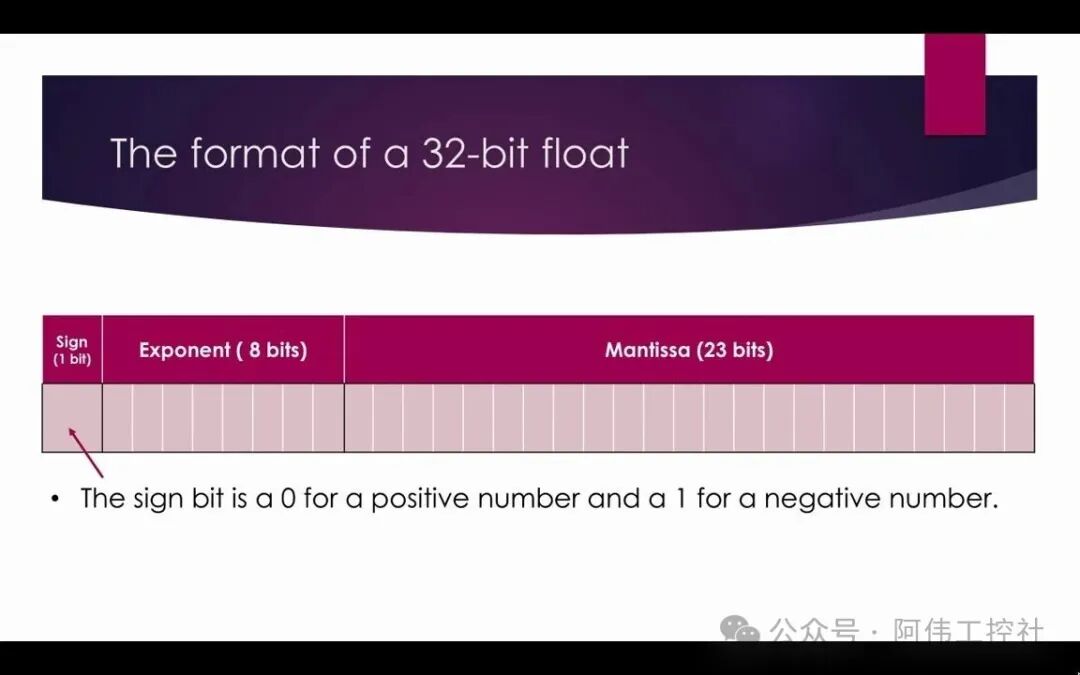
(In the register structure diagram, bit31 is the sign bit S, bits23-30 are the 8-bit exponent e, and bits0-22 are the 23-bit mantissa m, visually demonstrating the physical layout of the “layered arrangement”)..
 Pitfall Guide: The “Safety Rules” of Data Conversion




In PLC data type conversion, error troubleshooting must follow standardized processes. Error troubleshooting flowchart The core steps are: monitor the ENO signal (instruction execution status, 0 indicates failure) → check if the source data exceeds the target type range → adjust the conversion instruction or data type definition. This process can quickly locate anomalies and reduce debugging cycles.
Data Conversion Safety Manual
① Data Overflow: The “Red Line” of Value Range
When the source data exceeds the target type representation range, overflow errors will occur. For example, converting 32768 to INT type (maximum value 32767) will result in erroneous values like -32768. A temperature control system in a food factory once experienced abnormal heating output due to sensor data (50000) exceeding the INT range, leading to a temperature control deviation of ±8℃.Solution: Before conversion, use the CMP instruction to check the data range, ensuring the value is within the target type interval (e.g., INT must be between -32768 and 32767)..
② Precision Loss: The “Invisible Loss” of Decimal Parts
When converting floating point to integer, the decimal is truncated by default (e.g., REAL type 3.1415 → INT type 3), and continuous operations may accumulate errors. In the pharmaceutical industry, a batching system experienced a deviation of 0.5kg per batch due to direct conversion of REAL type flow values to INT, leading to overages after 10 batches.Key Recommendation: Use the ROUND instruction to round (3.14→3, 3.6→4) instead of direct truncation; in precision-sensitive scenarios (like weighing and measuring), it must be enabled..
③ Address Conflicts: The “Occupancy Rules” of Consecutive Registers
32-bit data (like double word MD100) occupies two consecutive 16-bit registers (MW100 and MW102). If MD100 and MW100 are used simultaneously, it will lead to data overwriting. A car production line experienced a speed display jump fault due to MD100 (storing motor speed) and MW100 (storing alarm codes) sharing addresses.Mandatory Requirement: 32-bit data must exclusively occupy consecutive registers; after clearly marking “MD100 (double word)” in the symbol table, it is strictly prohibited to define sub-addresses like MW100, MW102..
Three Principles to Avoid Pitfalls
-
Range Pre-Check: Use CMP instruction to confirm that source data is within the target type range (e.g., INT ≤ 32767);
-
Precision Control: Use ROUND for rounding in critical scenarios instead of direct truncation;
-
Address Exclusivity: 32-bit data (MD/DBD) must be stored consecutively, prohibiting the use of sub-addresses.
A chemical reactor project implemented the above rules, reducing downtime caused by data conversion from an average of 3 times a month to 0, confirming the decisive role of standardized conversion processes in system stability. In actual programming, it is recommended to combine monitoring tables to verify conversion results in real-time, prioritizing the handling of error branches where ENO=0 to avoid data risks from the source..
 Brand Instruction Quick Reference Table: A “Dialect Comparison Table” Across PLCs




Data type conversion instructions for different PLC brands are like “dialects” in the industrial field—different names but serving the same core tasks. Whether it’s Siemens’ rigorous naming, Mitsubishi’s concise code, or Rockwell (AB)’s functional reuse, mastering the correspondence of these “dialects” enables engineers to quickly switch thoughts in cross-brand projects. Below is a core conversion instruction comparison table for the three major brands, helping you navigate the “meridians” of data type conversion.
Table
Copy
| Function | Siemens (S7 Series) | Mitsubishi (FX Series) | Rockwell (AB Logix) | Example | Notes |
|---|---|---|---|---|---|
| Integer to Floating Point | INT_TO_REAL | FLT (16-bit → 32-bit) | MOV (implicit conversion) | INT_TO_REAL IN:=MW0 OUT:=MD20 | Siemens supports sign extension; Mitsubishi FLT must be used with floating point operation instructions; AB MOV automatically changes data format during transfer. |
| DINT_TO_REAL | DFLT (32-bit → 32-bit) | – | DFLT D10 D20 (Mitsubishi) | Mitsubishi DFLT is used for converting 32-bit integers to floating point without precision loss. | |
| Floating Point to Integer | REAL_TO_INT (rounding) | INT (truncation) | TRN (truncation) | REAL_TO_INT IN:=MD20 OUT:=MW40 | Siemens defaults to rounding; Mitsubishi INT directly truncates the decimal part; AB TRN has no rounding function. |
| – | DINT (32-bit truncation) | MOV (rounding) | INT D20 D30 (Mitsubishi, truncation 3.8→3) | AB MOV’s rounding behavior depends on the processor model. | |
| Rounding to Integer | ROUND | ROUND | ROUND | ROUND D20 D50 (Mitsubishi) | Siemens ROUND outputs as double integers; Mitsubishi ROUND requires floating point operation support (like FX3U model). |
Key Reminder: The AB PLC COP instruction is a typical “trap”—it only performs bit-to-bit copying (like directly copying the 16 bits of INT to the low 16 bits of REAL) without involving data format conversion. If mistakenly used as a conversion instruction, it may lead to value parsing errors (for example, integer 100 copied via COP may display as garbled floating point). Actual conversion must use the MOV instruction, which completes format conversion through implicit operations..
Although these instructions have different names, they essentially solve the “value representation” conversion problem: whether converting the “precise scale” of integers to the “continuous range” of floating points or landing the results of floating point operations as integer control signals, the core logic always revolves around “data precision” and “operational needs”. For example, in temperature control scenarios, Siemens users use<span><span>INT_TO_REAL</span></span> to process the 16-bit integer signal from the sensor, while Mitsubishi users use<span><span>FLT</span></span> instruction to achieve the same function, ultimately serving the floating point operation needs in PID regulation. Remember this “dialect comparison table”, and you will find that cross-brand programming is merely a change in “expression”.
 Conclusion: The “Data Foundation” of Precise Control




Let’s return to the “temperature anomaly” problem mentioned at the beginning—when the 4-20mA current signal from the sensor is incorrectly operated directly in integer format, the fluctuations after the decimal point in temperature are ruthlessly truncated, ultimately leading to frequent misjudgments in the temperature control system. However, when we grasp the core logic of data type conversion: converting the integer (INT/DINT) of the analog input through instructions like FLT to floating point (REAL), and then combining the sensor range to calculate the actual temperature value, this “accurate sensor data → improved control precision” link becomes clear. As many practical cases have verified, correct data conversion can reduce temperature collection errors from ±2℃ to ±0.1℃, which is the precision that industrial automation pursues in the “thousandth of a millimeter”..
Data types are the “language foundation” of PLCs, and conversion is the “grammar rule”. Just as engineers must understand the standards of mechanical drawing to read blueprints, PLC programmers must clarify the storage rules of integers and floating points, and be familiar with the safe usage of conversion instructions like CONV and FLT, to ensure the control system “understands” every signal from the sensor. Ignoring this foundation, even the most complex control logic may cause the system to “speak nonsense” due to issues like data overflow and precision loss—such as using 16-bit INT to store engineering values exceeding 32767, or mixing BCD code with binary format in temperature calculations..
From temperature sensors in the workshop to robotic arms on the production line, behind every precise action is the silent construction of a “digital bridge” by data type conversion. When we can skillfully master the standardized processing flow from “sensor signal → integer → floating point → engineering value” and quickly adapt to the instruction differences between Mitsubishi and OMRON in cross-brand programming, we can truly make PLC “speak right” for every value. After all, the precision revolution in industrial automation always begins with the utmost respect and control over data..