Hello everyone, as the saying goes, knowing both yourself and your enemy will lead to victory in a hundred battles. Recently, I downloaded several PLC upper computer software for synchronous testing and analysis of functionality, performance, principles, UI design, etc. The software I am analyzing at this late hour is the Auto Station Pro from Invt, a company based in Shenzhen.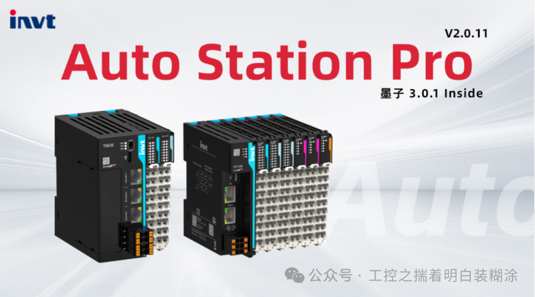 Invt has been in the automation industry for many years, and its frequency converters were once nationally leading. It is now a prominent player in the domestic power electronics industry. Compared to frequency converters, its servo drives, PLCs, and motion controllers are not as well-known or have a significant market share. I have taken out its PLC upper computer for dedicated learning and comparison.First, when I opened the PLC upper computer, the interface was as shown below. My first impression is that the entire software architecture is reminiscent of VC6.0, and it is likely implemented using VC6.0 + QT GUI.core. I mean, can we get a designer to beautify this interface a bit and make it look more sophisticated?
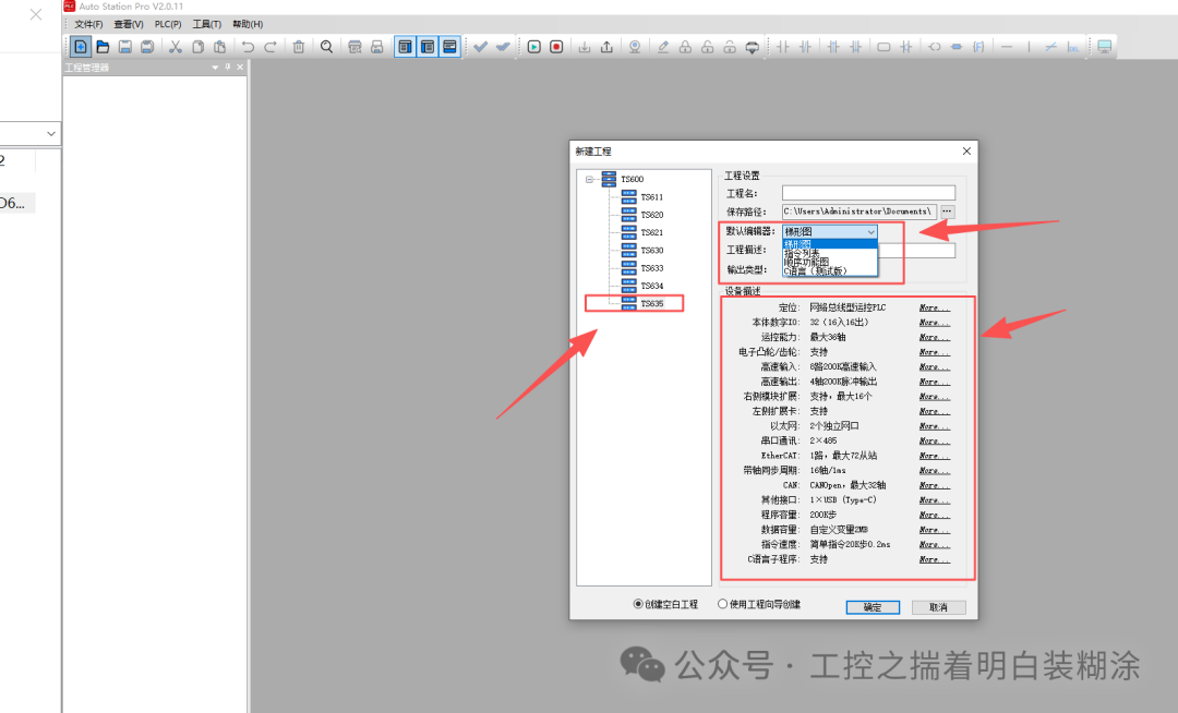
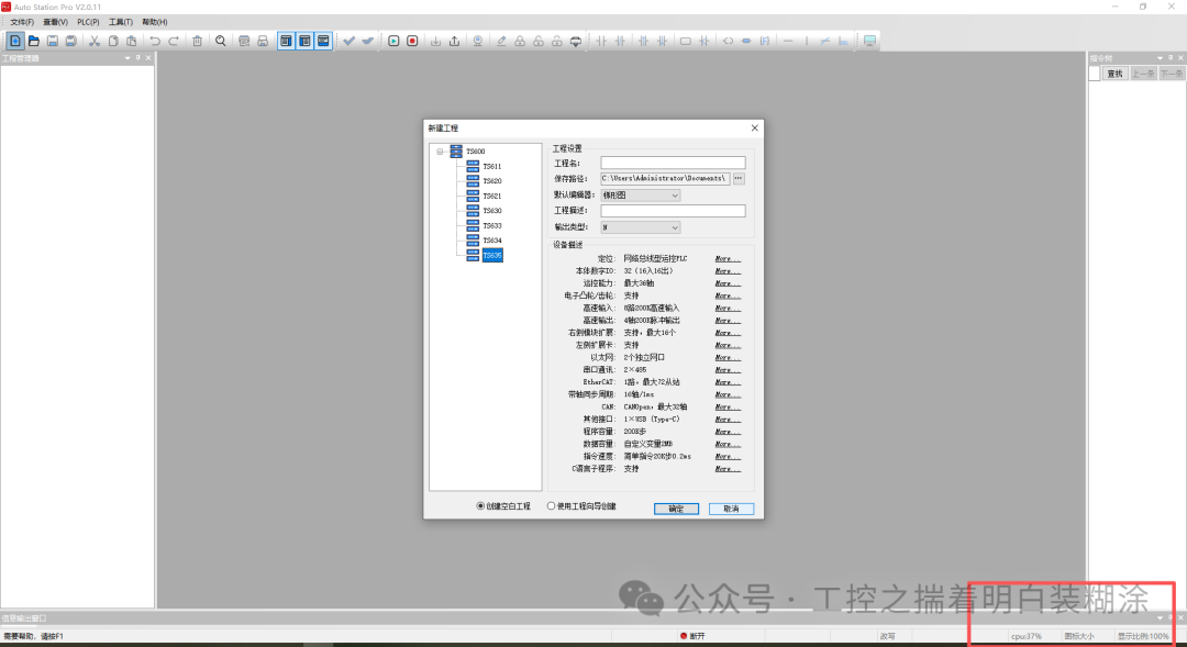 One small highlight is in the lower right corner; this PLC upper computer IDE can display the CPU usage of the PC, which I have never seen in other PLC upper computers.As we all know, the computers we use for PLC automation programming have many software installed, consuming considerable resources on the PC. This small tip can help engineers monitor the dynamic resource consumption of the PC’s CPU in real-time.I created a new project to test the functionality, selecting the latest TS635 model. I noticed that the programming language can be selected right from the start, divided into Ladder Diagram (LD), Instruction List (IL, which is rarely used now), Sequential Function Chart (SFC), and C language (beta version);Analyzing the supported functions of the PLC’s CPU module, it supports motion control, electronic cam, high-speed pulse input/output, 16-axis 1MS response synchronization, and a 20K execution time of 0.2ms (this metric is related to the PLC’s hardware chip + OS, and the execution time of the MCU and SOC machine cycle also has an impact).Why is there no ST language? Does this indicate that the architecture of this PLC IDE is relatively enduring, similar to many years ago? I personally speculate that the PLC compiler at that time did not integrate the syntax analysis function for ST language, simply parsing the Ladder Diagram (LD) into C language through the compiler.
 After creating the project, I configured it using Ladder Diagram programming. As for the related PLC upper computer IDE, I won’t elaborate on the programming. For other functionalities, I temporarily categorized them into five types.
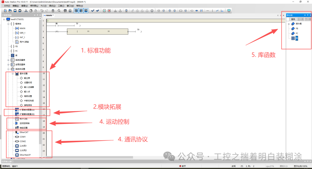 From the perspective of the system block design subproject, the implemented functions resemble the American style of small PLCs from 30 years ago. From system stop, task scan time, priority response, PLC probe interrupts, to variable declaration and allocation for power failure retention, it is small but complete.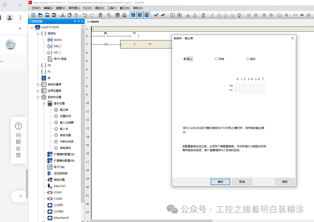
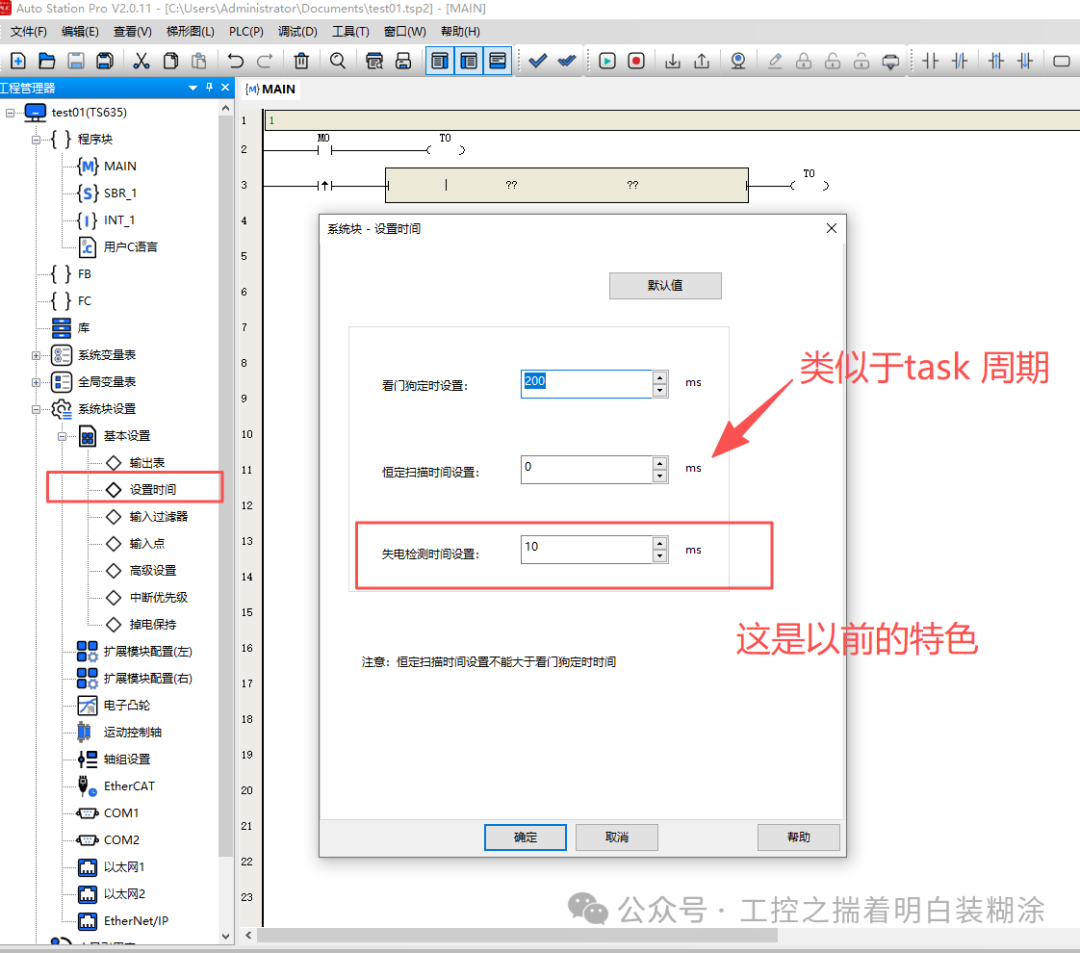 Generally speaking, modern medium to large PLCs implement power failure retention functions mainly through hardware storage chips like MRAM. In contrast, general small PLCs, due to cost constraints and architectural design requirements, typically utilize specific hardware storage space, which is why the power failure retention storage space of small PLCs is relatively small and compact. This is also why small PLCs have various M elements, input/output elements, etc., aimed at ensuring memory allocation and data access.
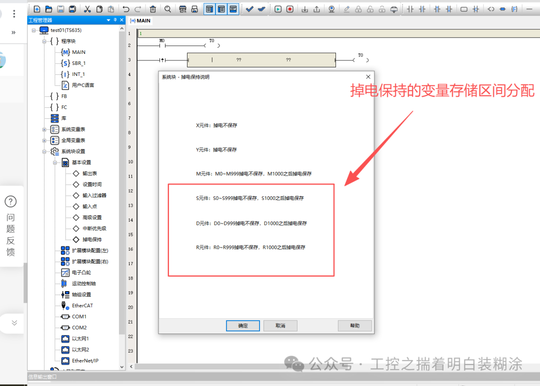 For the PLC’s IO module expansion function, I configured it, which achieved a general drag-and-drop configuration that is relatively user-friendly. Additionally, it provided parameter configuration for modules like SSI, overall reliability, and error diagnosis prompts for configuration modules. A small flaw is that there is no prompt for the configured IO modules on the right side of the expansion module; I suggest improving this in the future and recommend other PLC manufacturers pay attention to this detail.
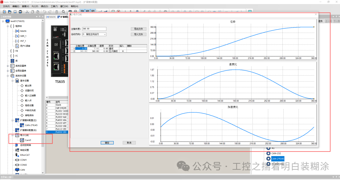
 Electronic cam function:The basic electronic cam function has been implemented. Friends familiar with motion control know that the implementation of electronic cams is based on a quintic polynomial algorithm, which derives multiple times from the cam table to calculate the coefficients of the quintic polynomial, and then plans the cam curve. Many years ago, I discussed with colleagues involved in frequency converter R&D about integrating electronic cams into frequency converters for all-in-one machines in the packaging and printing industry.From the following image, the basic electronic cam can be realized, and the UI is also acceptable. If we want it to be perfect:1. The number of electronic cam tables can be increased;2. There is a lack of jerk parameter configuration for acceleration and deceleration, and a lack of position configuration and comparison for master and slave axes. This can be referenced from CODESYS or Omron’s CX-ONE configuration. Personally, I feel that Omron’s UI and configuration are the best.
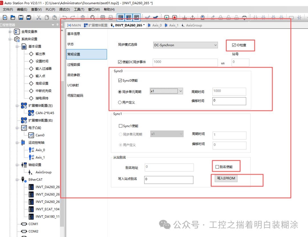
 I added several DA200 servos and configured the axis parameters and axis group settings.EtherCAT parameter configuration, supports the master station’s scanning function for slave stations. Relatively speaking, it is similar in style to CODESYS, supporting DC synchronization and parameter adjustment, as well as PDO and SDO parameter configuration. Of course, I am also wondering whether the implementation of the EtherCAT master station uses a pure software solution like SOEM/IGH or an FPGA IP core solution.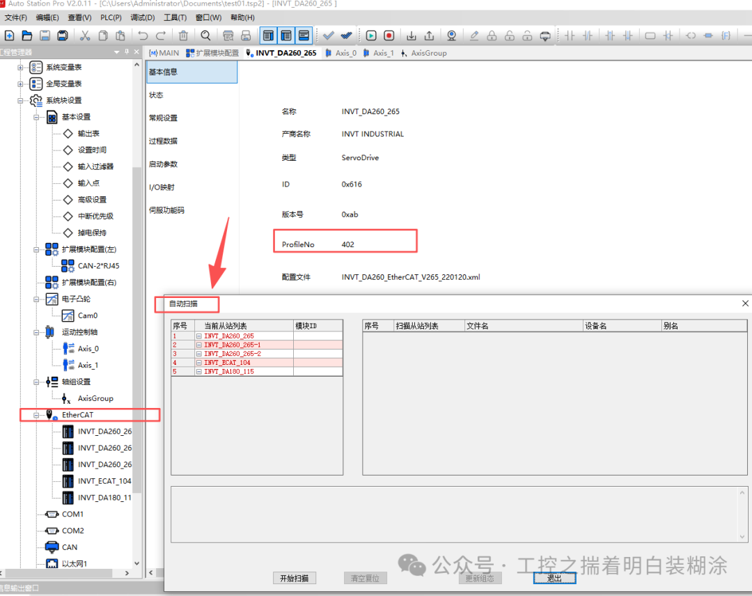
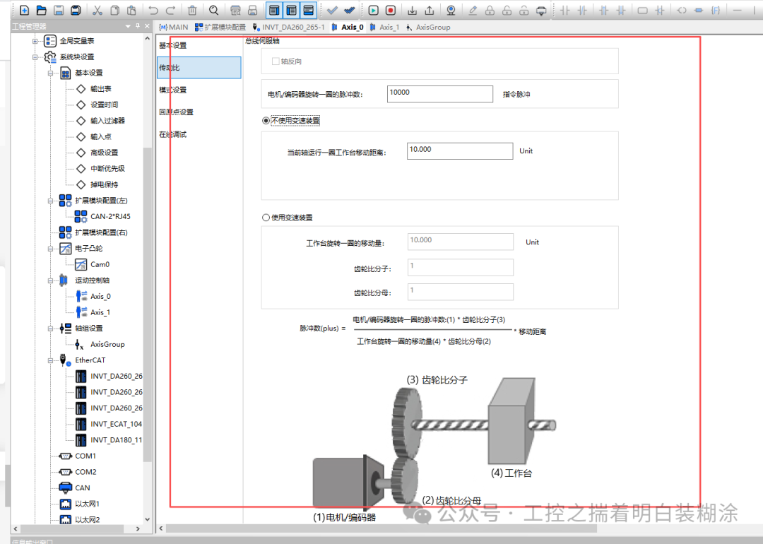
 In terms of parameter configuration for the axis group and gear ratio, it is evident that the R&D personnel put in effort, similar to the usage habits of Omron, Beckhoff, etc.
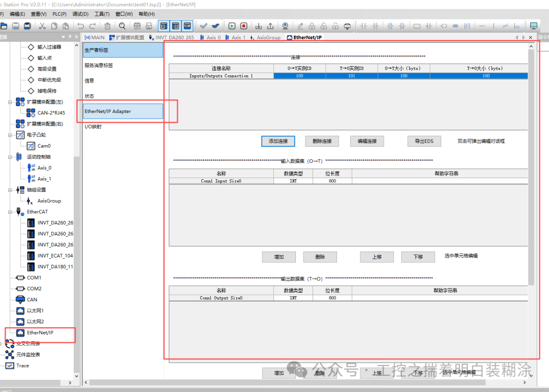
 What surprised me the most is that this PLC supports EtherNet/IP communication, which is impressive. I configured it briefly; since I do not have the PLC hardware, I could only understand the functionality through the PLC upper computer IDE configuration. Overall, it is still quite good.I previously introduced the development of EtherNet/IP slaves, which I had productized many years ago. In my spare time, I am also working on the development of EtherNet/IP master stations and code specifications, and I have made some progress, but I cannot be complacent and must learn more from my peers.
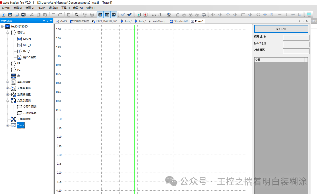
 This PLC has other functions such as cross-referencing, monitoring, tracing, etc., which are also quite mature, so I won’t elaborate further.
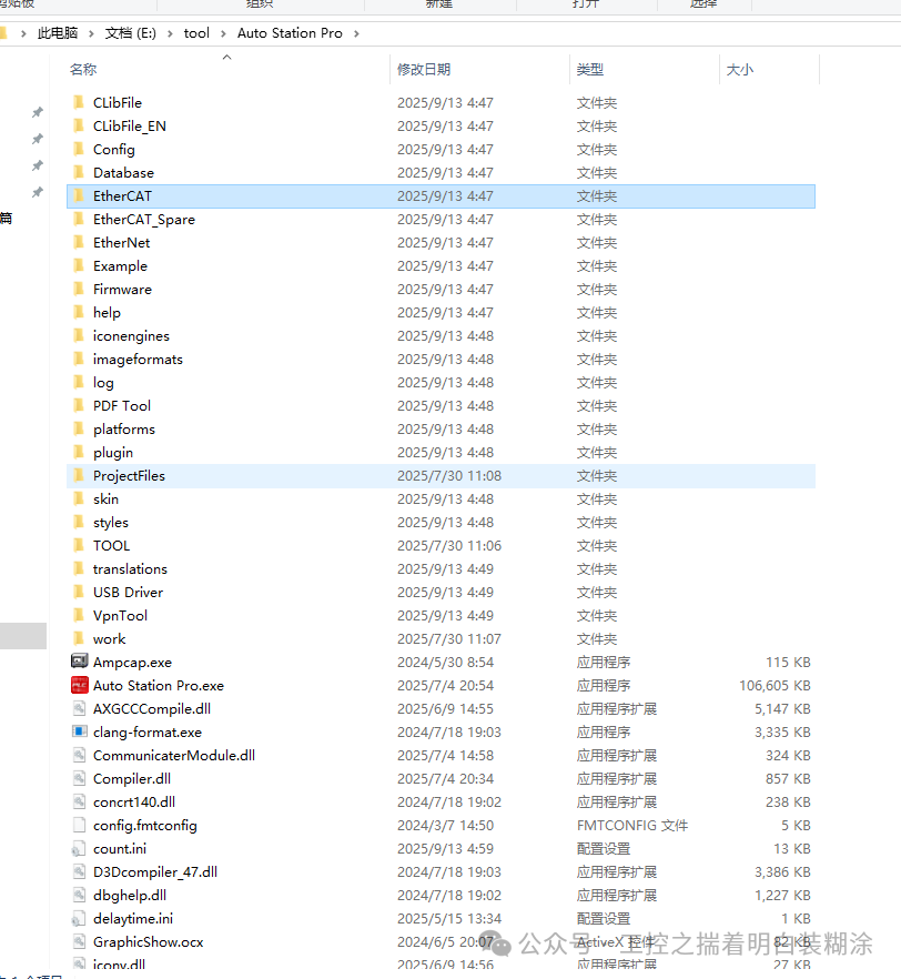
 I also took a look at the installation directory of the PLC software, examining the XML files imported for EtherCAT, the parsing methods, related clang parsing, compiler.dll, etc. Out of respect for intellectual property, I won’t elaborate further.
 Finally, let me summarize for the readers and friends at Invt:1. Domestic PLCs are doing well. I approach this analysis with an encouraging mindset, hoping that domestic PLCs from any manufacturer continue to improve.2. The UI of Auto Station can be beautified further.3. The programming languages should be diversified, especially ST (referencing CODESYS, etc.), but this involves the development of the compiler and whether the software architecture needs to be restructured.4. The secondary development of user libraries and protection of intellectual property are crucial issues that I hope will improve.5. Communication efficiency between multiple PLCs is currently not reflected, as they are mostly OEM standalone devices; the functionality for collaborative work among multiple PLCs has yet to be demonstrated.I was unable to sleep at 3:30 AM, so I got up and opened my computer to conduct this analysis. Now I am a bit tired and want to sleep. If I have said anything incorrect, I hope everyone can understand and be forgiving.Lastly, I have an idea: I want to establish a WeChat group for technical discussions, mainly to discuss industry technical issues, purely for exchange and learning, to improve together. Interested friends can message me privately. After I establish the WeChat group, I will share the group number with everyone. Thank you.